


Using (Apache) NuttX Buttons Subsystem
Previously in this EmbeddedRelated article, we saw how to use LEDs Subsystem on NuttX testing on RaspberryPi Pico. In the same way we avoided using GPIO Subsystem to control LEDs we can avoid using GPIO Subsystem to read Buttons inputs. That is right, NuttX has an Input Device Subsystem like Linux and today we will learn how to use it.
![]()
Quick Links
- Part 1: Getting Started with (Apache) NuttX RTOS - Part 1
- Part 2: Getting Started with (Apache) NuttX RTOS Part 2 - Looking Inside and Creating Your Customized Image
- Part 3: Getting Started with NuttX RTOS on Three Low Cost Boards
- Part 4: Using GPIO in (Apache) NuttX RTOS
- Part 5: Using (Apache) NuttX USERLED Subsystem
- Part 6: Using (Apache) NuttX Buttons Subsystem
- Part 7: How to use I2C devices in (Apache) NuttX: Scanning for Devices
- Part 8: How to use I2C devices in (Apache) NuttX: Adding support for an I2C device in your board
- Part 9: How to use SPI devices in NuttX RTOS
Buttons are one of the simplest user input interface and after the famous "hello world LED" example they are probably the second thing that someone learning Embedded Systems development will try to integrate on his/her microcontrolled board.
Although in "baremetal" development someone just reads directly from a GPIO Input to know if the button is pressed or released, in an RTOS like NuttX you don't need to, because the Buttons Subsystem is way more flexible and easy to use. It supports features like detecting multiples buttons, naming buttons, software debouncing, etc. This way your application just need to wait for an event that will happen when your button is pressed or released, nothing else.
Unfortunately the RaspberryPi Pico board doesn't same any user accessible button. In fact, the only button in the board (BOOTSEL) is not connected to any pin of the RP2040 microcontroller. Instead, it is connected in the CS pin of the SPI Flash and when pressed during the power-on/reset of the board will induce fail to boot from that flash and will force the boot ROM to boot over USB. This way the user will see the USB Mass Storage Disk and it lets to flash the RP2040 very easily.
So, since we don't have any usable button in the board we will mount a small circuit in a breadboard with two buttons, that we will call "VOL_UP" and "VOL_DOWN". You could use these buttons in your application to increase or decrease the audio volume for example.
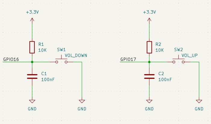
Note that we added a resistor and a capacitor for each button, these components will work as hardware debouncing to avoid ripples when user press and button and that could cause cause extra activations. Remember I said that the Button subsystem supports software debouncing, so could avoid using this circuit, but please do a favor to yourself: never waste processing time doing things that can be done better by the hardware at almost no extra cost.
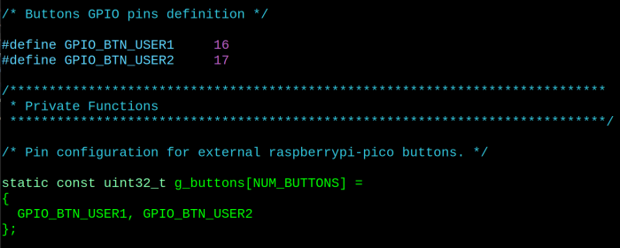
In this example we are using GPIO 16 as button 1 (VOL_DOWN) and GPIO 17 as button 2 (VOL_UP). These pins are defined at boards/arm/rp2040/raspberrypi-pico/src/rp2040_buttons.c this way:
We can start the build process clearing the previous configuration:
$ make distclean
Now you can configure your board to use the Buttons subsystem, but this time instead of using an external USB/Serial I will explain how you can use the usbnsh to access the NuttX terminal directly:
$ ./tools/configure.sh raspberrypi-pico:usbnsh
Run "make menuconfig" to enable the Button support:
$ make menuconfig
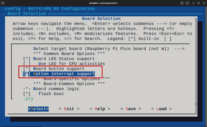
Enter inside "Board Selection --->" and enable these two options to enable the board buttons support:
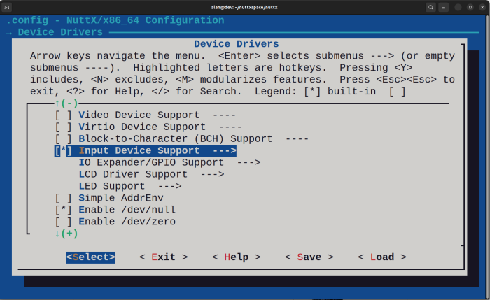
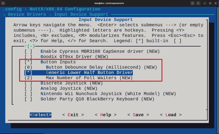
Inside "Input Device Support" scroll down and enable "Buttons Inputs" and "Generic Lower Half Button Driver":
Finally exist from "Device Drivers" and enter inside "Application Configuration --->", "Examples --->" :
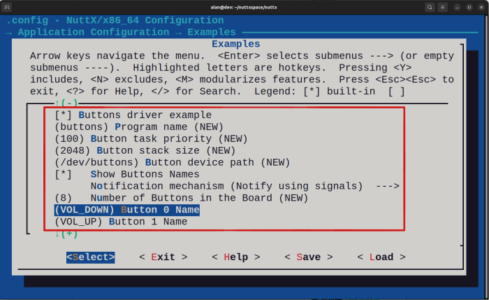
As you can see you enabled "Show Buttons Names" and used "VOL_DOWN" for our Button 0 and "VOL_UP" for Button 1. You can exit and save now and compile it:
$ make -j
...
LD: nuttx
Generating: nuttx.uf2
tools/rp2040/elf2uf2 nuttx nuttx.uf2;
Done
Flash this "nuttx.uf2" as explained in the previous tutorials.
As I said earlier, because this time we are not using the USB/Serial adapter, but the raspberrypi-pico USB as serial console device, you need to change your terminal console tool (minicom, picocom, teraterm, etc) to use /dev/ttyACM0 instead of /dev/ttyUSB0.
First confirm your computer detected it correctly after flashing the firmware:
$ sudo dmesg
...
[41720.996537] usb 3-3.2.4: New USB device found, idVendor=0525, idProduct=a4a7, bcdDevice= 1.01
[41720.996550] usb 3-3.2.4: New USB device strings: Mfr=1, Product=2, SerialNumber=3
[41720.996554] usb 3-3.2.4: Product: CDC/ACM Serial
[41720.996557] usb 3-3.2.4: Manufacturer: NuttX
[41720.996560] usb 3-3.2.4: SerialNumber: 0
[41721.006922] cdc_acm 3-3.2.4:1.0: ttyACM0: USB ACM device
As you can see /dev/ttyACM0 was created, so you can use for exemplo minicom configure to /dev/ttyACM0 at baudrate 115200 8n1.
Before the "nsh>" prompt show up you need to press
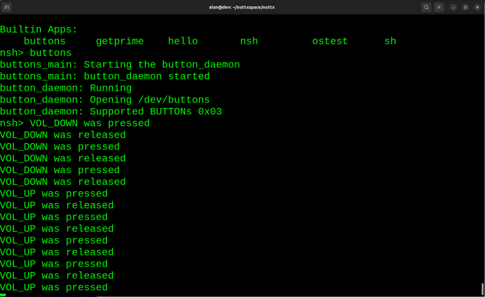
Amazing!!! You learned a new feature from NuttX that will enable you to create applications to interact with users using physical buttons.
That's it! In the next tutorial you will learn how to use I2C devices on NuttX. Stay tuned!


- Comments
- Write a Comment Select to add a comment
To post reply to a comment, click on the 'reply' button attached to each comment. To post a new comment (not a reply to a comment) check out the 'Write a Comment' tab at the top of the comments.
Please login (on the right) if you already have an account on this platform.
Otherwise, please use this form to register (free) an join one of the largest online community for Electrical/Embedded/DSP/FPGA/ML engineers:


