


How to use I2C devices in (Apache) NuttX: Scanning for Devices
Previously in this EmbeddedRelated article, we saw how to use Buttons Subsystem on NuttX using a RaspberryPi Pico board. Now we will change from user input device (buttons) for something more generic: I2C protocol. NuttX supports a lot of I2C devices (sensors, displays, EEPROMs, I/O Expanders, I2C multiplexers, and many more). And most important: because NuttX is a Linux-like RTOS you will find the very familiar i2ctool to search for devices in your I2C bus. So, lets to get started!
![]()
Quick Links
- Part 1: Getting Started with (Apache) NuttX RTOS - Part 1
- Part 2: Getting Started with (Apache) NuttX RTOS Part 2 - Looking Inside and Creating Your Customized Image
- Part 3: Getting Started with NuttX RTOS on Three Low Cost Boards
- Part 4: Using GPIO in (Apache) NuttX RTOS
- Part 5: Using (Apache) NuttX USERLED Subsystem
- Part 6: Using (Apache) NuttX Buttons Subsystem
- Part 7: How to use I2C devices in (Apache) NuttX: Scanning for Devices
- Part 8: How to use I2C devices in (Apache) NuttX: Adding support for an I2C device in your board
- Part 9: How to use SPI devices in NuttX RTOS
As most of ours readers know, the I2C protocol was invented by Philips Semiconductors in the 80's to interconnect devices inside circuit boards. Compared to current interfaces standard this protocol is slow: the Standard mode (Sm) uses 100 kbit/s; Fast mode (Fm) use 400 kbit/s; Fast mode plus (Fm+) at 1 Mbit/s, High-speed mode (Hs) at 1.7 Mbit/s or 3.4 Mbit/s, Ultra-fast mode (UFm) at 5 Mbit/s.
Although there are many I2C modes, at end of day you will work mostly with Standard mode devices (100 kbit/s) and Fast mode devices (400 kbit/s).
In order to support an I2C device on NuttX, first your microcontroller architecture needs a driver that will interact with the I2C controller inside this microcontroller and will control all I2C operations / transactions. For the RP2040 microcontroller used on Raspberry Pi Pico board, this driver is located at nuttx/arch/arm/src/rp2040/rp2040_i2c.c.
So, when your board initializes it will call a "rp2040_i2cbus_initialize(port);" to initialize the I2C port of your microcontrooler (RP2040 has two I2C ports: I2C0 and I2C1). That function will return a pointer to a "struct i2c_master_s", this is a generic i2c master instance, that is used by all I2C devices supported by NuttX. No matter what is your microcontroller or your board, it will return an i2c master instance that is used as a generic "glue" to interface with any I2C device supported by NuttX.
For instance, if you want to use a BMP280 pressure sensor, you will call "bmp280_register(devno, i2c);". The first parameter is the number you want assign to your BMP280 sensor inside NuttX (i.e. "/dev/press0"), if you are a Linux user probably you are used to see something like "/dev/ttyUSB0", "/dev/fb0", etc. The second parameter "i2c" is the i2c_master_s instance returned previously by that rp2040_i2cbus_initialize().
Since now you know how things work under the hood of NuttX, we can move to the next steps: 1) connect the BMP280 to the RaspberryPi Pico and 2) configure the NuttX with "i2ctool" to verify if our device (i.e. BMP280 sensor) is correctly connected in the I2C Bus before you try to register it in our code.
Wiring the sensor to the board is very simple:

The NuttX configuration also is straight forward, as we will see:
Start clearing your previous configuration:
$ make distclean
We will use the NSH over USB to avoid connecting an external USB/Serial adapter to the serial pins, so run:
$ ./tools/configure.sh raspberrypi-pico:usbnsh
Now we can select the options to get the "i2ctool" working:
$ make menuconfig
Enter inside "System Type --->" and select "I2C Master", "I2C0" and "I2C character driver"
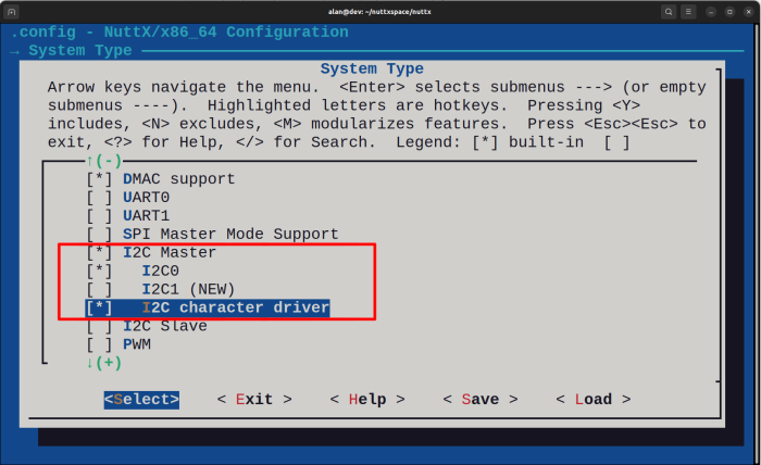
Case you decide to add the BMP280 on I2C1 bus, you need to select "I2C1" instead of "I2C0", or, case you want to have devices on both I2C ports you need to select both.
You can "Exit" from "System Type" and enter inside "Device Drivers --->", as you can see "I2C Driver Support" is automatically selected (pay attention at "-*-" in front of it, instead of "[*]")
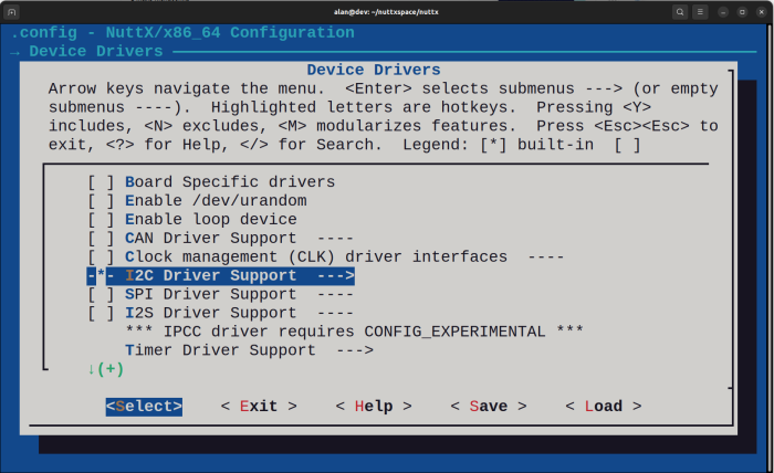
Some chips doesn't select it automatically (i.e STM32), in this case you need enable "I2C Driver Support" manually and enter inside it and enable "I2C character driver", to create the "/dev/i2c0". In our case, this option also is enabled automatically.
We don't need to enable the BMP280 driver now, because all we want is run "i2ctool" and see if the device appears in the bus. So you can "Exit" from "Device Drivers" to return to main menu.
Enter inside "Application Configuration --->" and then "System Libraries and NSH Add-Ons --->" and enable "I2C tool --->"
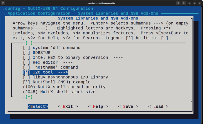
Enter inside "I2C tool --->" and change the "Maximum bus number" to 1, since RP2040 has only I2C0 and I2C1:

Finally you can select: "Exit
At this point we can compile:
$ make -j
If you see this message at the end:
PICO_SDK_PATH must be specified for flash boot
It means you forgot to include the SDK in your PATH, you need to include it, in my case:
$ export PICO_SDK_PATH=/home/alan/pico-sdk
Compile again and you need to see these lines at the end:
LD: nuttx
Generating: nuttx.uf2
tools/rp2040/elf2uf2 nuttx nuttx.uf2;
Done.
As you did in previous article, press and hold the Raspibbery Pi Pico BOOTSEL button and connect the USB cable. A "RPI-RP2" virtual disk should appear on your file manager, the copy nuttx.uf2 to it.
After the file is flash the green LED will turn on, you can also run "sudo dmesg" to confirm that USB CDC/ACM was detected correctly.
Run minicom (or your preferred terminal console tool) and press "Enter" three time to let the "NSH>" appears. If you type "help" or "?" you will see that "i2c" tool application appeared:

You can type "i2c bus" to verify which ports are enabled. We will see only I2C0 enabled because we only enabled that I2C port in the menuconfig, if you enable I2C1 too you should see both with "YES" value.

Finally we can run "i2c dev -b 0 0x03 0x7f" to search for some device in the bus. Some important notes: "-b 0" means we want to use "i2c0"; "0x03" is the initial I2C address to search and "0x7f is the final address.
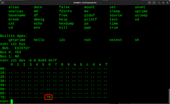
As you can see it found our BMP280 sensor at I2C address 0x76. If instead using the BMP280 sensor you had added an SSD1306 OLED display (yes, that small display used on MMDVM Duplex Hotspot Module) you should see it at 0x3c address.
That is it, in the next tutorial we will see how to add the BMP280 sensor in your board configuration and read pressure information from it.


- Comments
- Write a Comment Select to add a comment
To post reply to a comment, click on the 'reply' button attached to each comment. To post a new comment (not a reply to a comment) check out the 'Write a Comment' tab at the top of the comments.
Please login (on the right) if you already have an account on this platform.
Otherwise, please use this form to register (free) an join one of the largest online community for Electrical/Embedded/DSP/FPGA/ML engineers:


