


Introduction to Microcontrollers - More On Interrupts
Quick Links
- Part 1: Introduction to Microcontrollers - Beginnings
- Part 2: Introduction to Microcontrollers - Further Beginnings
- Part 3: Introduction to Microcontrollers - Hello World
- Part 4: Introduction to Microcontrollers - More On GPIO
- Part 5: Introduction to Microcontrollers - Interrupts
- Part 6: Introduction to Microcontrollers - More On Interrupts
- Part 7: Introduction to Microcontrollers - Timers
- Part 8: Introduction to Microcontrollers - Adding Some Real-World Hardware
- Part 9: Introduction to Microcontrollers - More Timers and Displays
- Part 10: Introduction to Microcontrollers - Buttons and Bouncing
- Part 11: Introduction to Microcontrollers - Button Matrix & Auto Repeating
- Part 12: Introduction to Microcontrollers - Driving WS2812 RGB LEDs
- Part 13: Introduction to Microcontrollers - 7-segment displays & Multiplexing
- Part 14: Introduction to Microcontrollers - Ada - 7 Segments and Catching Errors
A Little More Detail About The Interrupt Mechanism
It's time to look a little closer at what happens in an interrupt request and response. Again this is in general terms, and different microcontroller designs may do things somewhat differently, but the basics remain the same. Most but not all interrupt requests are latched, which means the interrupt event sets a flag that stays set even if the interrupt event then goes away. It is this latched flag that actually generates the interrupt request. The latched flag may be cleared in two different ways. First, it can always be cleared manually by user code, usually by writing a '1' to the flag bit position in the associated register. Second, the flag may be cleared automatically when the interrupt is responded to and the ISR begins to run. If this is the case it means that there is no need for the ISR to explicitly clear the flag, as it will already be cleared by the time the ISR starts to run, but check the datasheet for any particular interrupt source to see if this is the case.
Any interrupt request flag that has been set, if the associated interrupt enable is set, is said to be "pending." If the microcontroller global interrupts are enabled, and one or more separate interrupts are enabled, the CPU hardware will automatically check all of these separate interrupt flags during the execution of every instruction. If only one flag is found set, at the end of the current instruction the CPU jumps to, or "vectors to," that interrupt's ISR. In doing so, the interrupt flag may be automatically cleared (depends on the design), the return address (address of the next instruction that was going to be executed) is saved, and perhaps some CPU flags are saved, and possibly some CPU registers are switched, and the ISR begins executing. Lots of perhapses and possiblys, so gotta read the datasheet!
If the request flags of more than one enabled interrupt are found set - that is, if more than one interrupt is pending - things get more complicated. There will always be a priority assigned to each interrupt source. This priority may be fixed in the hardware or it may be configurable by the user program. The pending interrupt with the highest priority is the interrupt that will be serviced (that is, who's ISR will run). The other interrupt request flags will stay set - that is, the other interrupts will remain in a pending state.
What happens next, with an ISR running and other interrupts pending, also depends on the CPU design (see a pattern here?). Some microcontrollers, such as the AVR, disable global interrupts as part of the interrupt vectoring process. Thus the ISR begins running with global interrupts disabled and any other pending interrupts "on hold." When the ISR ends, the global interrupt state will be set as part of the state restoration that happens at the end of an ISR. Setting the global interrupt state here is legitimate since it had to be enabled for the ISR to have been entered in the first place. So now the next instruction of the interrupted background code will start to run, and the CPU will recognize that there are one or more pending interrupts, and again the highest priority pending interrupt will be serviced at the end of that instruction, with any others remaining pending, and so it goes.
Come Back Later - What Happens With An Interrupt Request If Interrupts Are Disabled?
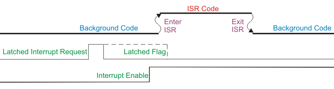
As mentioned, interrupt events are quite often latched. This means that when the event occurs, a flag is set and that flag remains set until some different action clears it. In particular, the flag remains set even when the setting event goes away. For example, we may get a low pulse on our external interrupt pin which sets the internal interrupt flag. Even if the pulse then ends (line goes back high) the interrupt request flag will remain set. This happens whether interrupts are enabled or disabled, either a particular interrupt or global interrupts. The flag will remain set until it is explicity cleared by code (usually by writing a '1' to the flag bit position in the associated register), or until the interrupt is enabled and serviced, at which point either the hardware or the user ISR will clear the flag.
One consequence of latched interrupt flags is that one can get a burst of interrupts serviced when interrupts are first enabled, if the interrupt conditions had previously been met. One situation where this could happen is with edge-triggered external interrupts, where the triggering edge may have occurred as a side effect of system initialization, or just due to fluctuations as all the electronics powers up. For reasons such as these it is often a good idea to clear any such interrupt flags before enabling global interrupts, to avoid responding to spurious interrupt requests. The best approach is to make it a general rule to ask yourself if a particular interrupt flag should be cleared just before your code enables that interrupt.
For a latched or edge-triggered interrupt, this drawing shows how the interrupt event sets the latched flag, which then generates an interrupt request when the interrupt is enabled, even if the interrupt event has since gone away. If this were a level-triggered interrupt, no interrupt request would be generated because the interrupt event has gone away by the time the interrupt is enabled.
Piling On - What Happens When An Interrupt Request Comes Inside An ISR?
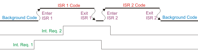
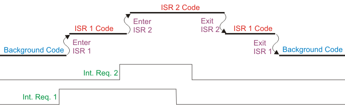
So far we've only talked about interrupts that interrupt background code. But what about an interrupt that tries to interrupt an ISR? For example, suppose we have two external interrupts enabled, INT1 and INT2. INT1 has interrupted and the INT1 ISR is executing, then along comes an interrupt request on INT2. What happens now?
Well, one of two things can happen. The new interrupt may be blocked until the INT1 ISR finishes, at which time it will be serviced. Or, if interrupts have been enabled inside the INT1 ISR, (or, for some microcontroller designs, if INT2 has been set to a higher priority than INT1) the INT1 ISR will be interrupted in just the same way that the background code was interrupted, and the INT2 ISR will run and when it is finished the INT1 ISR will resume running.
This drawing shows the first behavior, with INT2 being held off until ISR1 finishes. Notice how ISR1 returns to execute one or more background code instructions before INT2 is responded to. Some processor designs, including the ARM Cortex, have special hardware that avoids that little wasted effort and will run ISR 2 immediately after ISR1 ends, without the short return to background code.
This drawing shows the second behavior, with INT2 interrupting ISR1. For an AVR this can happen if ISR1 re-enables global interrupts inside of itself. For the STM32 this can happen if INT2 is a higher priority than INT1.
First Things First
It is important in writing your ISR that you have some sense of what needs to be done right away, at the start of the ISR, and what can be done later. Quite often you'll want to change one or more GPIO outputs or registers, and/or read one or more GPIO inputs or registers, at the very start of the ISR. Then you can finish whatever other housekeeping must be done in the ISR. This rule depends very intimately on what the interrupt source is, and what the desired ISR action is, and in most cases on what the associated hardware needs. In the simple interrupt-driven LED program from the last chapter, the LED output is changed first, and the then next interrupt edge is changed and the current interrupt flag cleared. In the case of a blinking LED this attention to sequencing is of course totally unimportant, but it illustrates the concept, and there will be ISRs where it IS important. Just keep in mind the general principle that you want to do first things first, and second things after that.
The Scary Side of Interrupts
I said in the last chapter that interrupts weren't magic. I take it back. Interrupts behave exactly like magic, and bad magic at that, if you don't reign them in. Interrupts can trash your data is ways that seem impossible. They can also refuse to execute code that is plainly written. But they're so useful - necessary, really - that we just have to write code that avoids their dangers.
Most of the problems with interrupts are related to their chief benefit, which is that running code can be interrupted at almost any time, and the code never knows it was interrupted. It is as if you can freeze time for the background code, do anything you want to the data or I/O, and then restart time for the background code. To offer an analogy, imagine you were about to sit in a chair. You look and see that the chair is available, then you turn around and start to sit down. Then time freezes for you and Scamp the Interrupt moves the chair, or puts a cake on it, and then time begins for you again. Only now, as you're about to touchdown on what you thought was a safe chair landing, the world as you thought you knew it has changed, and not for the better. That's what badly designed software using interrupts can be like. Your code can experience things like values becoming corrupted without warning, but only once every 17 days. Good luck debugging that! Better to save your sanity and understand the reasons behind such potential problems, and prevent them before they can happen.
Data is the Problem (or, Background Code Hates Surprises!)
In our interrupt-driven LED program, we never tried to pass data between the background code and the ISR (ignoring the settings of the configuration registers). This is actually a rare circumstance for an interrupt. Most ISRs will involve passing data to background code and/or retrieving data from background code, and this is where things can go bad. Problems are guaranteed to occur whenever background code is in the middle of accessing data and an interrupt comes along and the associated ISR then accesses the same data.
As an example, imagine an system where an external trigger generates an interrupt, and in the ISR a new temperature and pressure value pair is read in from some external sensors. In the background code, some valve positions are calculated based on the current temperature and pressure. Now imagine this sequence in the code:
- Background code loads temperature
- Interrupt comes along, updates temperature and pressure
- Background code loads pressure
- Background code calculates valve positions based on temperature and pressure
What has just happened is that the background code has now loaded an old temperature and a new pressure, and will calculate valve positions based on this mismatched data, which is neither valid for the previous measurement nor for the current measurement. It is corrupted data. The details may change, but the basic problem is the same: either the ISR or the background code thinks it is getting a vaiid set of data, but in reality it gets corrupted data - some new, some old.
Things can even get worse than that. Even a single piece of data can be corrupted. Imagine an 8-bit microcontroller that receives a 16-bit data value from an ISR. To load a 16-bit data value on an 8-bit device, two 8-bit loads are required. Depending on the CPU design, the sequence may be to read the lo 8 bits (least significant byte or LSB) followed by the hi 8 bits (most significant byte or MSB), or it may be MSB followed by LSB. In any case, imagine that the background code has loaded the first 8 bits (let's say the LSB), then an interrupt comes along and the ISR writes out a new 16-bit value to the memory variable. At the end of the interrupt, the background code resumes and loads the 2nd 8 bits (MSB), but now it has a 16-bit value built from the LSB of the previous value and the MSB of the new value. This is neither the old value nor the new value, but some corrupted combination of the two. Here is a numeric example:
- 16-bit variable X holds 0x1234
- Background code loads LSB of 0x34
- Interrupt triggers and ISR sets X to 0x3421, then returns
- Background code loads MSB of 0x34
- Now background code contains an X value of 0x3434 (!!!)
There's yet a third way that an interrupt can result in corrupted data. Remember our 2nd LED Blinky program that contained the following innocent line:
PORTB ^= (1<<PB0);
This is what is called a read-modify-write (RMW) sequence. What actually happens is this:
- Read PORT value into CPU
- Modify the value in CPU (XOR with 1 in this case)
- Write modified CPU value back out to PORT
Here is the actual AVR compiler output for the above line of C code ("in" is a read instruction, "out" a write instruction, "eor" an exclusive or instruction):
      PORTB ^= (1<<PB0);
91 e0     ldi r25, 0x01   ; 1
88 b3     in r24, 0x18
24 89 27  eor r24, r25
88 bb     out 0x18, r24   ; 24
Imagine that the background code has just read the PORT value, which has PB0 set to '0', and an interrupt occurs, and the interrupt ISR writes out a new PORT value setting PB1 to '1'. Then the background code resumes and writes out a modified PORT value that has set PB0 to '1' but has not changed any other bits. This newly-written output does not reflect the PORT output change made in the ISR. Our PORT value is now trashed - PB1 is '0' and it should be '1':
- PORT contains value of 0b00
- Background code reads PORT
- Interrupt triggers ISR which sets PORT to 0b10, then returns
- Background code modifies its value of PORT to 0b01 and writes it out
- Now PORT contains 0b01 instead of the correct 0b11
The exact same thing can happen with a RMW sequence on a memory location. After all, a PORT is just a form of memory location. So here is yet another way that interrupts can result in corrupted data. Are you scared yet? You should be. Things you never would think twice about doing in normal sequential programming can blow up in your face when interrupts are involved. ISRs must share access to data with background code to be useful, but this very shared access will clobber you in multiple ways if it is not strictly controlled.
Disabling Dangerous Interrupt Around Critical Section - AVR Version
This code snippet shows just the main() function of our previous AVR_INT1 program, but with code to disable and then re-enable the INT0 interrupt around the one-line critical section that performs a RMW on the output port. The STM32 disable and re-enable would be the same, but using the EXTI_IMR register.
int main(void)
{
  DDRB = (3<<PB0);      // LED output on PB0 (blinking) and PB1 (interrupt-driven)
  PORTB = (3<<PB0);

  MCUCR = 0b10<<ISC00;  // negative edge trigger
  GIFR = 1<<INTF0;      // clear any pending interrupt
  GICR = 1<<INT0;       // enable INT0

  sei();                // enable all interrupts

  while(1)
  {
    GICR &= ~(1<<INT0); // disable INT0 - could use cli() here instead
    PORTB ^= (1<<PB0);  // toggle PB0 in the background - critical section!
    GICR |= (1<<INT0);  // re-enable INT0 - could use sei() here instead

    delay(80000);
  }
}
Make It Stop!
OK, are you put off from interrupts forever? Don't be, there is a solution. What is required in all such cases is to simply prevent such overlapping accesses to data. To do this, any code, when beginning to access shared data, must be allowed to have uninterrupted access to that data. In the case where the data is shared by one or more interrupts, this means that those particular interrupts must not be allowed to run while the background code is accessing the shared data. Either the background code or the ISR must wait its turn for access to the data. Such a safe data access, where there is no possibility of interruption or corruption, is called an "atomic access", implying that the access is indivisible. Any section of code that must have indivisible access to data (or any other resource, for that matter) is called a "critical section."
The heavy-handed but easy way to implement this solution is to simply disable all interrupts when shared data is being accessed, and this may be an adequate solution. A more well-behaved solution is to just disable the interrupt(s) that would access the shared data in question, while still leaving other interrupts to enabled. After all, an interrupt that can't corrupt the data being accessed cannot be a threat.
Another solution is to prevent the sharing of data in the first place. If only one piece of code (background or ISR) has access to a piece of data, that data can never be corrupted. For example, if only background code or the ISR accessed the output PORT, the situation above could never occur. Sometimes it is possible to rearrange a program so that sharing is avoided, but this may just mean that some other data now needs to be shared instead.
Here is our interrupt-driven LED program for the AVR with suitable protection against RMW corruption of PORTB. All that is done is to disable the data-sharing interrupt before background code modifies PORTB and re-enable it immediately after. This actually buys us nothing over just disabling and enabling global interrupts in this simple case (because we have no other interrupts enabled anyway), but it shows the technique. Specific interrupts or global interrupts, do the analysis and choose your approach.
Hardware To The Rescue
Now that we've just seen how you need to protect yourself from shared access to GPIO outputs, we have good news. More and more microcontrollers are addressing the problem of atomic access to GPIO outputs with special hardware. The STM32 is a good example of this. Besides having the standard input and output GPIO registers, the STM32 has two more registers per port. One, the port reset register, allows immediate clearing of selected bits without changing any other bits, and the other, the port set register, allows immediate setting of selected bits without changing any other bits. Since these actions are not interruptable there can be no RMW corruption. But it gets even better. The port set register uses the low 16 bits to identify the port bits to set, but it also uses the high 16 bits to identify port pins to clear in the same instruction. This means that a single instruction can atomically set or clear any designated combination of output bits. Very nice! This shows that sometimes you need to move away from your standard method (XORing the output port bit) and take advantage of whatever special goodies your particular uC has to offer.
Using Chip-Specific Hardware To Remove Critical Section - STM32 Version
This code snippet also shows just the main() function, this time of the STM32_INT1 program. It adds some logic to use the atomic set and clear output port registers. By doing this we eliminate the critical section entirely, so we do not need to disable and re-enable the interrupt which could corrupt such a critical section. The AVR version could do the same thing - eliminate the critical section entirely - by using either the write-to-PIN-register method of toggling, or using the set-bit and clear-bit instructions (which the AS6 compiler should generate anyway, for single bit changes). It shows that sometimes you need to move away from your standard method (XORing the output port bit) and take advantage of whatever special goodies your particular uC has to offer.
int main(void)
{
  uint8_t flag = 0;

  RCC->CFGR = 0b100 << 24;      // HSI, 8 MHz, SYSCLK->MCO

  RCC->APB2ENR |= RCC_APB2ENR_IOPAEN; // enable PORTA for button input
  GPIOA->CRL = (0b0100);        // CNF=1, MODE=0 (floating input)

  RCC->APB2ENR |= RCC_APB2ENR_IOPCEN; // enable PORTC for LED output
  GPIOC->CRH = 0b0010 | (0b0010 << 4);     // CNF=0, MODE=2 (2MHz output) (PC8,PC9)

  AFIO->EXTICR[0] = 0;          // EXTI0 is PA0
  EXTI->RTSR = 1;               // rising edge, EXTI0
  EXTI->IMR = 1;                // enable EXTI0
  NVIC->ISER[0] = (1 << EXTI0_IRQn);


  while (1)
  {
    if (flag)
    {
      GPIOC->BRR = (1<<9);      // atomic clear PORTC bit 9
      flag = 0;                 // toggle flag
    }
    else
    {
      GPIOC->BSRR = (1<<9);     // atomic set PORTC bit 9
      flag = 1;                 // toggle flag
    }

    delay(80000);
  }
}
Some microcontrollers, including the AVR, take a different approach to this problem. The AVR has single instructions that can set or clear an individual bit in certain regions of memory, including the GPIO ports. Any good AVR compiler should generate those instructions when it sees that a single GPIO bit is being AND'ed to 0 or OR'ed to 1. Thus for setting or clearing a single GPIO bit, these instructions will do the job atomically even though the high level code seems to imply a RMW cycle. Unfortunately, this only applies to setting or clearing one bit at a time, unlike the STM32 capability to operate on multiple bits at one time. Newer models of the AVR also have another atomic trick, which is that by writing '1's to certain PIN bits of a GPIO register, those bits of that port which are configured as outputs will toggle. That is, by writing '1's to the port input register, any port bits set as outputs will toggle. It's quirky, but it can be useful.
Many other uC registers, in various uC models, also have a form of atomic access. This involves the ability to clear an event or interrupt flag that has been set by hardware without touching any other bits in the register. Normally this would require a RMW cycle to zero the desired bits, but as we have seen, RMW can lead to data corruption. Thus, instead, this form of atomic access allows us to write a '1' to any bit we want to clear, and a '0' to any other bits (those bits not to be touched). This works because we generally only want to clear the bits in question since they are usually set by the hardware. You will run across this "write '1' to clear a register bit" paradigm rather often, so be aware of it. And just because nothing should ever be easy, some uCs switch things around so that a '0' clears the register bit while a '1' does nothing. I can't say it enough - read the datasheet!
To Volatile Or Not To Volatile
Just when you thought it was finally safe to use interrupts, here's a new gotcha. This is not a fundamental problem, but a warning about how some compilers work. In the case of some compilers, such as avr-gcc used in Atmel Studio, if a variable is used in both background code and an ISR, that variable must be declared as 'volatile' or the optimizer will get overly helpful with the result that writes to the variable seem to not happen. So find out whether your compiler requires 'volatile' for such shared variables, and if it does, post a big note on your monitor until using the keyword becomes second nature.


- Comments
- Write a Comment Select to add a comment
To post reply to a comment, click on the 'reply' button attached to each comment. To post a new comment (not a reply to a comment) check out the 'Write a Comment' tab at the top of the comments.
Please login (on the right) if you already have an account on this platform.
Otherwise, please use this form to register (free) an join one of the largest online community for Electrical/Embedded/DSP/FPGA/ML engineers:


