


Introduction to Microcontrollers - 7-segment displays & Multiplexing
Quick Links
- Part 1: Introduction to Microcontrollers - Beginnings
- Part 2: Introduction to Microcontrollers - Further Beginnings
- Part 3: Introduction to Microcontrollers - Hello World
- Part 4: Introduction to Microcontrollers - More On GPIO
- Part 5: Introduction to Microcontrollers - Interrupts
- Part 6: Introduction to Microcontrollers - More On Interrupts
- Part 7: Introduction to Microcontrollers - Timers
- Part 8: Introduction to Microcontrollers - Adding Some Real-World Hardware
- Part 9: Introduction to Microcontrollers - More Timers and Displays
- Part 10: Introduction to Microcontrollers - Buttons and Bouncing
- Part 11: Introduction to Microcontrollers - Button Matrix & Auto Repeating
- Part 12: Introduction to Microcontrollers - Driving WS2812 RGB LEDs
- Part 13: Introduction to Microcontrollers - 7-segment displays & Multiplexing
- Part 14: Introduction to Microcontrollers - Ada - 7 Segments and Catching Errors
Doing the 7 Segment Shuffle
The 7 segment display is ubiquitous in the modern world. Just about every digital clock, calculator and movie bomb has one. The treadmills at my gym have 6 or 7, each one displaying 3 or 4 digits. What makes the 7-seg interesting is that it presents an opportunity to make a trade off between GPIO (output pins) for time. Every 7-seg display requires 8 outputs (the 7 segments and usually either a decimal point or a colon). Thus a 4 digit display requires 32 outputs, and a 6 digit display requires 48 outputs. We microcontroller users generally guard our supply of GPIO pins jealously. If you are able to devote 48 GPIO pins to a 7-seg display, you're probably paying more for the uC than you need to. In addition, you'll need 48 current-limiting resistors and, unless your uC can directly drive all those segments, you'll need 48 driver transistors to get the proper current drive through the display LEDs (LCD 7-seg displays are another beast entirely).
You could use special 7-seg driver chips to reduce the number of output lines and replace the transistors, but it's hard to imagine when those would be economical. So the usual solution is to "multiplex" the digits of the display. This means to turn on one at a time, extra brightly, and scan through all the digits fast enough that the eye blurs the ON and OFF periods together and doesn't see any flicker. Now you have to have just one set of segment drive lines (8 GPIO) because you're only ever driving one set of segments at a time, and one set of digit drive lines (4 or 6 in our example). This means you need 12 GPIO vs. 32 for a 4 digit display, and 14 GPIO vs. 48 for a 6 digit. You also only need 8 current limiting resistors (and perhaps driver transistors) along with, in most cases, a driver transistor for each digit. The overall savings are considerable.
What does that "extra brightly" mean, exactly? Well, it's all a function of how the eye perceives brightness. You can roughly assume that if a constant segment current of X mA gives you your desired brightness, then N*X mA (where N is the number of digits) is the current you want to drive through a segment, for 1/N of the total time. In real life you'll probably just start playing with the current limiting resistor values looking for the highest values (lowest current) that gives you acceptable brightness. Of course your uC GPIO pins or driver transistors have to be rated to supply that N*X mA current, so that sets an upper limit to how bright you can drive the display. Equally important, your digit driver has to be able to source or sink 8*N*X mA, for the case that all 8 segments are turned on. Luckily, you can find very efficient displays these days, where even just 1 or 2mA of average current per segment may be enough.
So, how fast do we have to scan the digits? I find 100/sec to be a good number for the display update rate. Some people like to go faster, but going faster than you need to just burns up CPU cycles for no purpose. Often you can get by with a lower number like 50-80/sec, but then some people may start to notice flicker, especially in certain lighting conditions. So let's use 100/sec and run the numbers. To display all 4 digits 100 times/sec means we display each digit in turn for 1/400 of a second or every 2.5ms. For 6 digits the number is 1/600 of a second or every 1.67ms.
Now every digit time we have to do the following:
- Turn off the previous digit
- Advance our bookeeping to the next digit (now the current digit)
- Get the segment pattern for the current digit
- Output the segment pattern
- Turn on the current digit
Note in particular that all digits are off when the segments are changed. If you don't do this you will get ghosting on the display. This whole update process might end up being a couple dozen CPU cycles. Keeping in mind that a 20MHz microcontroller could execute nearly 50,000 instructions in 2.5ms, and a 100MHz uC nearly 250,000, we see that a couple of dozen cycles is a very low CPU load, less than 0.1%. This low CPU load, along with the savings in hardware, is what makes multiplexing attractive.
It's important at this point to understand how NOT to do this digit updating. Some external (to the display update) process will have generated an integer value between 0 and 9999 (let's assume 4 digits, positive values only). What we do NOT want to do in our digit update is to convert this integer value into separate digits and then grab the segment pattern for the digit we're updating. Converting an integer to separate digits takes some time, and it only needs to be done when the value is updated (maybe every quarter second or less often), certainly not every 2.5ms. What this means for our code is that the conversion of integer to digits should be a part of the code that provides the display value to the display code. To determine the best encoding for these digit values, we need to think about the segment patterns and how we will represent them. The segments are universally labeled A to G, along with DP if that is included. Here is the segment mapping (courtesy Wikipedia):
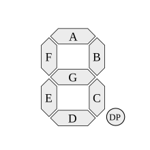
Thus for example, to display the value 7, you would activate segments A, B and C. Value 4 would be B, C, F and G, and so on. Very conveniently, we can store the segment patterns as 1 byte per value. This suggests that the segment patterns be stored in a byte array, either 10 elements (for the decimal digits) or 16 elements( hexadecimal digits). We might also want to add another value to represent all segments off, so as to blank the entire display, or blank leading digits. Finally, we may want to add another value to signify a minus sign (segment G).
Now we just have to assign a bit position to each segment. The two obvious choices are to go in A-G,DP order starting with D7, or go to in the same order starting with D0. For the board I designed, I chose to start with D0, so the segment array would look like this (in digits 0-9 order):
static u8 Seg_array[] = {0x3F, 0x06, 0x5B, 0x4F, 0x66,
                         0x6D, 0x7D, 0x07, 0x7F, 0x6F};
Since we want each digit value to be an index into our Seg_array, it makes sense (at least from a C background) to make the digit values 0 through 9. Note that this is not the same as the character values '0' through '9', which you would get from an itoa-type function. For convenience in converting the integer values to digit values, our first attempt uses sprintf, which does produce ASCII digit values. We convert those ASCII digit values to indexes by subtracting '0' from them. Later we'll look at a few options that are faster and smaller than sprintf.
Our display is a 4-digit common cathode display, meaning we drive the segment lines high and the digit lines low to light up the selected segments. The display is "clock format" meaning it has a colon between the 2nd and 3rd digits like a clock. It doesn't have any decimal points, unfortunately. The display is mounted on a board that connects to my motherboard via a 16-pin ribbon cable.
To show the multiplexed display in action we'll do a 1/10 second counter on an AVR in C (wish I had those decimal points!). Then we'll look at a few Ada approaches in the next tutorial.
Mission Creep
Our C version will be (was going to be) dirt simple, except that I keep thinking of fun things to add. Start with a 2.5ms digit update interrupt (100/sec display update rate). The 1/10 second counter could clock off the digit update interrupt, with 40 interrupts yielding exactly 100ms. In general always look for ways to use any timer interrupt for additional purposes. But I've decided to add the capability to slow down the digit update rate so you can see the flicker yourself. In that case we need to divorce the digit update rate from the 1/10 second counter, so we will use T3 for the latter, the tenths interrupt (the AVR is the ATmega1281). One small but important point is that the faster interrupt (T1) has higher priority than the slower interrupt (T3). This is built into the AVR design and cannot be changed - you can see the priority order in the datasheet. As a general rule, the higher the rate of a repetitive interrupt, the higher its priority should be. In our particular example, you're more likely to notice a delay in the service of the 2.5ms interrupt (digit flicker) than in the service of the 100ms interrupt.
In the tenths ISR, four buttons are also read (this is an example of using a timer ISR for multiple purposes). Button 1 (top left) clears the timer and resets the digit update rate to 100/sec. The next button, button 2, pauses the timer. Button 3 restarts the timer. Button 4 is the new addition, the "flicker button". Each press (it repeats at the interrupt rate) lowers the display update rate by 1/sec, and displays the new display update rate. This way you can lower it until you start to notice the effects in different lighting and via peripheral vision, and then reset everything by pressing button 1. Barrels of fun, and instructive too!
The only big unknown is the time it takes to convert the 1/10 second count to the correct 4-digit array index values. We might think of doing the conversion in the 100ms ISR, but that could yield problems. While our 100ms ISR is running, our 2.5ms interrupt is blocked, and if that happens we may see flicker in the display, as one digit stays on longer than it should, and the next one goes on shorter than it should. For this reason, we will choose to figure out a way for it to execute in the background when needed, while the 2.5ms interrupts keep updating the display. This keeps the 100ms ISR as short as possible. We can use our classic ISR-set, background-read flag to tell the background code whenever there's a new value to convert - that is, whenever the value is cleared or incremented.
No Problem, We'll Fix It In Software
Run and hide whenever you hear this (and you will hear it). It means there's a problem with the hardware, and they're hoping (expecting, really) the software people can make it all better. Well, we have a good example of that here. The 7-segment board connects to the motherboard via a 16-pin connector that, for the STM32VLDiscovery board, sensibly provided PA0-7 and PB12-15 - perfect for driving a 7-segment display. But I chose to demonstrate the C code with the AVR board, and the AVR board is a collection of compromises, attempting to match up the STM32 board comms interfaces (USART, SPI, I2C) first, then matching up any remaining GPIO with whatever AVR GPIO is left. The result is that the PA0-7 pins on the connector map to AVR PD4,PE1,PE0,PE7,PF0,PF1,PF2,PF3. Yes, it really is that bad. Furthermore, the digit bits PB12-15 match up as PB0,PB1,PB3,PB2. Did you catch that? Hey, no problem, we'll fix it in software, right?
Well, our digit ISR will take more cycles than a clean hardware design, but we definitely can fix this in software. We just have to map our segment and digit data bits to the appropriate AVR port bits. That means lots of masking and shifting, anding and oring. It turns out we have the same sort of mapping problem with the STM32F4 board that runs Ada, so in the next tutorial we can see an Ada way of handling it. In the meantime the code has a PROPER_HW_DESIGN flag to show how much simpler it would be if the segments were all sensibly mapped to one port, and if the digit lines were consecutive.
And now, our 1/10 second counter with 4 digit multiplexed display:
/*
 * _7Seg.cpp
 */


#include "defs.h"
#include <avr/io.h>
#include <avr/interrupt.h>

#define DIGIT_RATE		400		// 2.5ms interrupts
#define PRESCALE1		64		// T1 prescale of 64
#define PRESCALE3		64		// T3 prescale of 64
#define DIG_OCR			(F_CPU/PRESCALE1/DIGIT_RATE)	// 625 for our values
#define NUM_DIGITS		4
#define SCAN_RATE		(DIGIT_RATE/NUM_DIGITS)

#define DIG_VAL			(SCAN_RATE*DIG_OCR)				// 100 refreshes/sec @ DIGIT_RATE and 4 digits

static u8 Dig_array[NUM_DIGITS];
static volatile u8 Update_flag = 0;
static volatile u16 Tenths = 0;
static volatile u16 Rate = SCAN_RATE;		// initial value


#define PROPER_HW_DESIGN	0		// 1 if the hardware people listened to the software people during the hw design

// digit update timer
ISR(TIMER1_COMPA_vect)
{
	static u8 Seg_array[] = {0x3F, 0x06, 0x5B, 0x4F, 0x66,
                                              0x6D, 0x7D, 0x07, 0x7F, 0x6F};
	static u8 Dig_mask_array[] = {0x01, 0x02, 0x08, 0x04};
	static u8 Digit = 0;

	u8 segments;
	u8 dig_index;

#if PROPER_HW_DESIGN
	PORTB &= ~(1 << Digit);
#else
	PORTB &= ~Dig_mask_array[Digit];	        // turn off previous digit
#endif

	Digit = (Digit == 3 ) ? 0 : Digit + 1;
	dig_index = Dig_array[Digit];
	if (dig_index < 10)						   // valid digit index
		segments = Seg_array[dig_index];        // first we fetch the value of the chosen digit, then we get the segment pattern for that value
	else
		segments = 0;                             // any other index results in blank digit

#if PROPER_HW_DESIGN
	PORTA = segments;
	PORTB |= (1 << Digit);
#else
	PORTD = (PORTD & ~(1<<4)) | ((segments & 1) << 4);	    // put segments(0) into PORTD(4)
	PORTE = (PORTE & ~(0x83)) | ((segments & 2) << 6) | ((segments & 4) >> 1) | ((segments & 8) >> 3);	        // segments(1)->PE7, (2)->PE1, (3)->PE0
	PORTF = (PORTF & ~(0x0F)) | ((segments & 0xF0) >> 4);	// segments(4-7) -> PF0-3
	PORTB |= Dig_mask_array[Digit];				// turn off previous digit
#endif
}

// 1/10 second timer
ISR(TIMER3_COMPA_vect)
{
	static u8 Run = 1;

	u8 keys;

	if (Run)
	{
		if (++Tenths > 9999)
		Tenths = 0;
	}
	Update_flag = 1;

	keys = ~(PINC | 0xF0);						// active switches on PC0-3 = 1, everything else = 0
	if (keys & 1)
	{
		Tenths = 0;
		Rate = SCAN_RATE;
		OCR1A = DIG_OCR - 1;					// original digit update rate
	}
	if (keys & 2)
		Run = 0;								// stop
	if (keys & 4)
		Run = 1;								// run
	if ((keys & 8) && (Rate > 1))
	{
		Rate--;								// slow down 1/sec
		OCR1A = DIG_VAL / Rate;
	}
}

void GPIO_init(void)
{
	DDRB = 0x0F;								// PB0-3 drive digits
	DDRC = 0x10;								// PC4 = pseudo PC10, switch row output
	DDRD = 0x10;								// PD4 = PA0 (segment)
	DDRE = 0x8B;								// PE0, 1, 7 = PA3, 2, 1 (segments), PE3 (PB0) is debug
	DDRF = 0x0F;								// PF0-3 = pseudo-PA4-7 (segments)

	PORTC = 0x0F;							// pullups on PC0-3, and PC4=0
}

void T1_init(void)
{
	OCR1A = DIG_OCR - 1;
	TIMSK1 = (1 << OCIE1A);					// for TIMER1_COMPA_vect
	TCCR1A = 0;
	TCCR1B = (1 << WGM12) | (3 << CS10);	// CTC mode, 64 prescale, timer starts here
}

void T3_init(void)
{
	OCR3A = (F_CPU/PRESCALE3/10) - 1;			// for 1/10 sec ints
	TIMSK3 = (1 << OCIE3A);					// for TIMER1_COMPA_vect
	TCCR3A = 0;
	TCCR3B = (1 << WGM32) | (3 << CS30);	// CTC mode, 64 prescale, timer starts here
}

int main(void)
{
	GPIO_init();
	T1_init();
	T3_init();
	sei();

    while(1)
    {
        //TODO:: Please write your application code
		if (Update_flag)
		{
			char buf[6];						// to hold 5 digits and EOS
			// using sprintf because it's easy and gives us formatted output that's easy to use
			if (Rate == SCAN_RATE)				// display either timer value or display update rate
				sprintf(buf, "%5u", Tenths);		// no leading zeros
			else
				sprintf(buf, "%05u", Rate);		// keep leading zeros

			Dig_array[0] = buf[1] - '0';			// convert ASCII to digit indexes
			Dig_array[1] = buf[2] - '0';
			Dig_array[2] = buf[3] - '0';
			Dig_array[3] = buf[4] - '0';

			Update_flag = 0;
		}
    }
}
So we have the T1 ISR doing the digit updating (the multiplexing), T3 ISR updating the 1/10 sec counter and reading the buttons, and the main loop converting the 1/10 sec value (or the digit update rate) into the format used by the T1 ISR. Initially I'm using sprintf to do the formatting because it can format into a fixed number of characters, e.g. it can format the integer 7 into " 7" or "0007". This is very convenient, and I don't want to write the code to duplicate this capability. Later we'll look at other conversion options.
Hey, How Do You Convert 1234 To 1234?
Converting data from a memory or computationally efficient format (e.g. 16-bit integers) into a format suitable for display is a common embedded requirement. The suitable format depends of course on the requirements of the display, but in this case we've settled on an array of digit indexes, one byte per digit. We've seen how to use sprintf to do this (followed by the conversion of the ASCII digits to digit indexes by subtraction of '0'). Here are a few other ways, if you want to try and roll your own. This might be because your uC doesn't support hardware division or even multiplication, and those routines can take up a lot of cycles of code. Here are two routines to give you an idea of the possibilities.
#define BLANK_DIGIT  10 // anything outside of 0-9

#if 1
void utoi(u8 * p, u16 val, u8 blank_lz)
{
	u8 digit;
	u8 blank_this_z = blank_lz;

	while (val > 9999)
	val -= 10000;							// toss out any leading ten-thousands

	digit = 0;
	while (val > 999)
	{
		val -= 1000;
		digit++;
	}
	if (blank_this_z && (digit == 0))
	    digit = BLANK_DIGIT;
	else
	    blank_this_z = 0;
	*p++ = digit;

	digit = 0;
	while (val > 99)
	{
		val -= 100;
		digit++;
	}
	if (blank_this_z && (digit == 0))
	    digit = BLANK_DIGIT;
	else
	    blank_this_z = 0;
	*p++ = digit;

	digit = 0;
	while (val > 9)
	{
		val -= 10;
		digit++;
	}
	if (blank_this_z && (digit == 0))
	    digit = BLANK_DIGIT;
	*p++ = digit;
	*p = val;
}

#else

void utoi(u8 * p, u16 val, u8 blank_lz)
{
	div_t result;
	bool blank_this_z = blank_lz;

	result = div(val, 10000);	// strip out ten thousands

	result = div(result.rem, 1000);
	if (blank_this_z && (result.quot == 0))
	    *p++ = BLANK_DIGIT;
	else
	{
		blank_this_z = 0;
		*p++ = result.quot;
	}

	result = div(result.rem, 100);
	if (blank_this_z && (result.quot == 0))
	    *p++ = BLANK_DIGIT;
	else
	{
		blank_this_z = 0;
		*p++ = result.quot;
	}

	result = div(result.rem, 10);
	if (blank_this_z && (result.quot == 0))
	    *p++ = BLANK_DIGIT;
	else
	{
		blank_this_z = 0;
		*p++ = result.quot;
	}
	*p = result.rem;
}
#endif

int main(void)
{
	GPIO_init();
	T1_init();
	T3_init();
	sei();

	while(1)
	{
		//TODO:: Please write your application code
		if (Update_flag)
		{
			// using sprintf because it's easy and gives us formatted output that's easy to use
			if (Rate == SCAN_RATE)				// display either timer value or display update rate
			    utoi(Dig_array, Tenths, 1);
			else
			    utoi(Dig_array, Rate, 0);

			Update_flag = 0;
		}
	}
}
The two functions utoi (for unsigned-to-index) take the destination u8 array, the integer value to be converted, and a flag indicating whether leading zeros are to be blanked. As you can see, only one of the functions is defined at any one time, depending on the #if state (0 or 1). The first utoi function avoids any multiplication or division, so it's a good choice if your uC doesn't have those operations in hardware. The second utoi function uses the neat library "div" function, which returns both quotient and remainder - very useful! I think the code is more elegant, but it does require divisions. The leading zero blanking code is the same in both functions.
Here are some numbers for the AVR, which does not have hardware division. sprintf code is 2508 bytes (total program size, not just the sprintf part) and the conversions took 80us. utoi#1 code (not using "div") is 1110 bytes total program size, and took between 3 and 16us, depending on the number being converted. utoi#2 code, using "div", is 1152 bytes total program size and took 60us. Perhaps unintuitively, on a part that does not support hardware division, the brute force subtract and loop approach takes less code space, and is about 6 to 10 times as fast as the other approaches.
Two Timers is Too Many
Timers are precious resources. Maybe we don't have two to devote to our little experiment. That's OK, we only need one, with two output compare registers. We'll use the "leapfrog" technique, advancing the OCR registers inside the ISRs, essentially using two output compare registers to get the equivalent of two timers. Here are the changes required: T3_init and the TIMER3_COMPA ISR have disappeared. T1_init now starts the timer in "normal" mode, and TIMER1_COMPA ISR just adds the OCR1A += leapfrog line. TIMER1_COMPB ISR is added, performing the same function as TIMER3_COMPA did. Our interrupt priorities are still correct, since the priority of T1 COMPA is higher than T1 COMPB. Here are the modified sections of code:
static volatile u16 Dig_ocr = DIG_OCR;		// digit update rate


#define PROPER_HW_DESIGN	0				// 1 if the hardware people listened to the software people during the hw design

// digit update timer
ISR(TIMER1_COMPA_vect)
{
<< same as before, with one additional line >>
	OCR1A += Dig_ocr;							// advance to next interrupt time
}

// 1/10 second timer
ISR(TIMER1_COMPB_vect)
{
	static u8 Run = 1;

	u8 keys;

	if (Run)
	{
		if (++Tenths > 9999)
		Tenths = 0;
	}
	Update_flag = 1;

	keys = ~(PINC | 0xF0);						// active switches on PC0-3 = 1, everything else = 0
	if (keys & 1)
	{
		Tenths = 0;
		Rate = SCAN_RATE;
		Dig_ocr = DIG_OCR;					// original digit update rate
	}
	if (keys & 2)
		Run = 0;								// stop
	if (keys & 4)
		Run = 1;								// run
	if ((keys & 8) && (Rate > 1))
	{
		Rate--;								// slow down 1/sec
		Dig_ocr = DIG_VAL / Rate;				// COMPA ISR will use this.  No collisions because both uses are ISRs
	}
	OCR1B += TENTH_OCR;					// advance to next tenths time
}

....

void T1_init(void)
{
	OCR1A = DIG_OCR - 1;
	OCR1B = TENTH_OCR - 1;
	TIMSK1 = (1 << OCIE1A) | (1 << OCIE1B);	// for TIMER1_COMPA_vect and TIMER1_COMPB_vect
	TCCR1A = 0;
	TCCR1B = (3 << CS10);					// normal mode, 64 prescale, timer starts here
}
So here's a video of the code running. Of course the scanning of the video record and playback totally interferes with the scanning of the display, so you really can't see what's going on. I noticed that for myself, I could not notice flicker looking straight at the display, in daytime indoor lighting, until it got down to 42/sec. Using peripheral vision I started to notice flicker around 48/sec.
Next time we'll try it in Ada, and also see how Ada catches nasty runtime bugs and can report the exact file and line number where the bug occurred.


- Comments
- Write a Comment Select to add a comment
Hello,
Parts 8, 9 and 11 do not show a PDF Doanload button. Could you please make them available?
Thank you!
-Roberto S.
To post reply to a comment, click on the 'reply' button attached to each comment. To post a new comment (not a reply to a comment) check out the 'Write a Comment' tab at the top of the comments.
Please login (on the right) if you already have an account on this platform.
Otherwise, please use this form to register (free) an join one of the largest online community for Electrical/Embedded/DSP/FPGA/ML engineers:


