


Introduction to Microcontrollers - Adding Some Real-World Hardware
Quick Links
- Part 1: Introduction to Microcontrollers - Beginnings
- Part 2: Introduction to Microcontrollers - Further Beginnings
- Part 3: Introduction to Microcontrollers - Hello World
- Part 4: Introduction to Microcontrollers - More On GPIO
- Part 5: Introduction to Microcontrollers - Interrupts
- Part 6: Introduction to Microcontrollers - More On Interrupts
- Part 7: Introduction to Microcontrollers - Timers
- Part 8: Introduction to Microcontrollers - Adding Some Real-World Hardware
- Part 9: Introduction to Microcontrollers - More Timers and Displays
- Part 10: Introduction to Microcontrollers - Buttons and Bouncing
- Part 11: Introduction to Microcontrollers - Button Matrix & Auto Repeating
- Part 12: Introduction to Microcontrollers - Driving WS2812 RGB LEDs
- Part 13: Introduction to Microcontrollers - 7-segment displays & Multiplexing
- Part 14: Introduction to Microcontrollers - Ada - 7 Segments and Catching Errors
When 2 LEDs Just Don't Cut It Anymore
So far, we've done everything in this series using two LEDs and one button. I'm guessing that the thrill of blinking an LED has worn off by now, hard as that is to imagine. What's more, we've just about reached the limits of what we can learn with such limited I/O. We have come to the point where we need to add some hardware to our setup to continue with additional concepts and microcontroller peripherals.
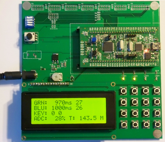
I ran into this problem very quickly after I had picked up my first STM32VLDiscovery board. 32 bit ARM Cortex M3, 128k flash, 8k RAM, timers galore, this was gonna be great! Well, not so much, at least not with the board all by itself. So I designed a docking board with a power source, 4x20 LCD character display, 4x4 button matrix, 4 LEDs, a potentiometer for ADC work, 4 configuration switches, and a bunch of expansion connectors. The STM32VLDiscovery would plug into this board and give a fun and useful system for working with that chip. As soon as I got back the first prototype boards I realized (that being the main function of prototypes, to remind you of things you should have done the first time) I should have added connectors for the STM32F0Discovery, the Cortex M0 version of the Discovery board, so there went a second round of prototypes. Then I decided I could build a board that plugs into the docking board and that holds an ATmega1281, making the docking board useful for Cortex M3, Cortex M0 and AVR training. Here is the result (with STM32VLDiscovery board plugged in):
It is this docking board that I will be using from this point forward in this tutorial series, for both AVR and STM32 examples. I've been playing with the idea of turning it into a Kickstarter project, but so far the entire world's supply sits in a drawer in my desk.
There is certainly no requirement for any person using this tutorial to have this docking board. What will be required is that the specified hardware (character LCD, button matrix, potentiometer, etc) be available in some form on whatever hardware platform is being used. Here is a list of the hardware blocks to be added:
4 x 20 LCD Character Display
These are your common HD44780-compatible displays, available everywhere. I recommend the larger 4x20 displays, but one could use smaller displays such as 2x16. Given the extra information you can fit on a 4x20, I think it is very much worth the few extra dollars for the larger display.
A 44780 display can connect using either 4 or 8 data lines, along with 2 or 3 control lines. I often use the minimalist connection of 4 data lines and 2 control lines, but with a bit more software work the 3rd control line can speed up communication with the display somewhat. If using 4 data lines, the best arrangement is to select the 4 upper bits of a port, e.g. PA4-PA7. The control lines can be any bits on any ports, but it is probably easiest to use the lower bits of the data port. On my docking board I also include a logic-level mosfet to turn the display backlight off and on (and even change its brightness via software or hardware PWM). If you want you can dispense with this output, but then I would suggest wiring the backlight to be permanently ON. Most such displays with their backlights off are very annoying to view, IMO.
4 x 4 Button Matrix
The button matrix requires 4 GPIO pins that can be configured as inputs and 4 that can be configured as outputs. It is easiest if each set of 4 is contiguous on the same port. Thus e.g. PA1,PA2,PA3,PA4 is preferable to e.g. PA0,PA3,PA4,PA7 (same port but not contiguous), and even more preferable than e.g. PA1, PA3, PB5, PB6 (multiple ports).
Since both the AVR and the STM32 can activate internal pullups on input pins, no external pullup resistors are necessary. If you were working with a uC family that did not have internal pullups, or if you were working in a high electrical-noise environment where lower-value ("stiffer") pullups were desireable for noise reasons, then you would have to add those pullups to each input line.
LEDs
The two LEDs on the STM32 boards are pretty minimal. The docking board parallels those two LEDs (the GPIO outputs that drive the onboard LEDs also drive LEDs on the docking board), and adds two additional LEDs for a total of 4 LEDs, placed across the 4 columns of the button matrix.
Configuration Switches
Configuration DIP switches are a useful tool to have on an educational microcontroller board. The user can use such switches to switch between algorithms to compare them, or to switch between master / slave, or transmitter / receiver, or to provide some form of board addressing, among other uses. 4 DIP switches are provided on the docking board. They are isolated with resistors so that if the pins connected to them are set as outputs, the outputs cannot be damaged no matter how the switches are set.
ADC (Analog to Digital Converter) Potentiometer
A simple 10k or 20k potentiometer is very useful in learning how to work with your microcontroller's ADC. The docking board has such a potentiometer with the center pin connected to a GPIO pin which can be configured as an ADC input. Note that not all GPIO pins can be used as ADC inputs - which ones can be used will be indicated on the datasheet. One end of the pot is connected to ground, and the other end is connected to the Vcc of the uC. Voltages on any ADC input must always be within the range of GND->Vcc to prevent damage to the microcontroller.
For further experimentation, additional ADC-capable GPIO are brought out to some of the docking board expansion connectors.
First Step - Adding An LCD Display
Adding a display is a smart first step because a display lets us see what is going on inside our uC, and is also a very useful debugging aid when things are going wrong. The display will require a minimum of 6 GPIO outputs, preferably all on a single port as discussed above. Also required is either a transistor (mosfet or bjt) to switch the backlight on or off, or else just hardwiring the backlight on. If using a transistor you will need to select a GPIO output to drive the transistor. This can be any bit on any port.
Many newbies seem to have difficulty programming the HD44780-compatible displays. I've never had a problem with them once I've read the datasheet carefully (you have downloaded a datasheet off the internet, right?). Perhaps the most crucial issue is to get the timing right. A particular delay is required after each initialization step, and whenever writing to the display in general. In addition, the enable ('E') pulses to the display must exceed a minimum duration. You must get these all of delays correct for the display to work. Longer is OK, but shorter and your display will not work at all, or it will be flakey. So, we're back to talking about delays. In particular, we need a delay of about 1us for the 'E' pulse (actually, >230ns), a delay of about 50us between each character write, and some delays in the milliseconds range. So let's refine our old delay() function to generate reasonably accurate microsecond and millisecond delays.
Tangent: Software Delays - Milliseconds
Remember that up to now we didn't much care what numbers we had to feed our software delay function, as long as we could get a human-perceivable LED blink. Now we have to do better. To run our LCD display, we have to produce a delay of around 1us, and a delay of around 50us, and delays in the ms range. The easier task is to write a ms_delay function, one that takes an argument for the number of milliseconds to delay. The reason it is easier is that there are a lot of clock cycles to work with in one millisecond. Anyway, here is the function, followed by the explanation:
void ms_delay(u16 d)
{
  while (d-- != 0)
  {
    volatile u16 i = MS_COUNT;
    while (i-- != 0)
      ;
  }
}
What we have done is to break the software delay loop into two loops. If we choose a value of MS_COUNT that causes the inner loop to execute in exactly 1ms, then the entire function will execute in "d" ms, as desired. So all that is required is to come up with a number for MS_COUNT. As is always the case with software delays, that number will depend on the uC clock rate - a higher clock rate means a larger number. We could figure a number by looking at the generated ASM code and counting the cycles for each instruction, but there's an easier way (for me, at least): fire up your oscilloscope (or beg or borrow one), and write a loop that calls ms_delay with some convenient number like 100. Then pick a number for MS_COUNT - 1000 is a good start. Toggle an LED just as before, using "ms_delay(100)" for the delay, and look at the scope. You will see a square wave where the signal toggles every so often. What we want is to see that toggle exactly every 100ms, but we will almost certainly not see that at first. We will have a longer or shorter interval, and from that we can make MS_COUNT shorter or longer until we get exactly (well, very close, which is good enough) to 100ms. For my AVR board, now running at a clock rate of 14.7456MHz, that number turns out to be 1053.
Now that we've done that work, we can actually come up with a formula that relates MS_COUNT to F_CPU. 14,745,600 / 1053 = 14,003.42. Now we have a simple definition of MS_COUNT:
#define MS_COUNT (F_CPU/14003)
Remember, this is for AVR, and is only valid for the compiler I used (avr-gcc in Atmel Studio 6, which is AVRGCC 3.4.1.95) and the optimization settings I used. That's one of the two curses of software delays - any change to clock rate or toolchain or settings can break them (the other curse is that they waste valuable cycles that could be used for doing the real work of your system).
There's another trick you can use to figure out MS_COUNT if you don't have access to a scope - become a scope yourself. To do this we'll extend the delay time way out past 100ms, to values a human can measure with some accuracy. Since the argument to ms_delay is a u16, we can time up to 65,535ms. 60,000ms is exactly one minute - convenient! So if we run our LED blinky program using ms_delay(60000), one entire blink cycle (ON-OFF) will take exactly 2 minutes. We can time 2 minutes pretty easily by eye and by clock. Then adjust your initial_count as follows:
MS_COUNT = initial_count*120/measured_time
So if the initial count was 1000 and one complete ON-OFF blink took 105 seconds, MS_COUNT would be 1000*120/105 = 1143.
Tangent: Software Delays - Microseconds
Unfortunately we can't take the same approach with microsecond delays, because there just aren't enough CPU clocks to work with in a microsecond. That's not a terrible problem because we only need two delays, >1us and >50us. The simplest solution is to just use a function like our earlier "delay" function, and use a scope to come up with the correct loop counts. The only change would be to modify the delay function argument from a uint32_t to a uint8_t, to get better time resolution (faster looping on an 8-bit uC). Using this approach you will be able to come up with a delay count that will generate a delay very close to 50us, and a very small delay count (1 is what I use) that will generate a delay that is rather longer than 1us, but that's not a problem, so just go with it. For my AVR, clock rate, tool chain and settings, those delay counts are 1 and 90. You will see both of these delay values in the listing to follow.
But What About The Included Delay Functions?
Users of avr-gcc know that there are some accurate built-in delay functions, _us_delay() and _ms_delay(), so why not use them? There are no doubt similar built-in functions included in some other compilers. The answer is, there is no reason at all not to use them, if you have them available. But not every compiler will have such functions, and it's a good exercise in learning how to write something equivalent, even if not as accurate.
Back To Our LCD Display
An HD44780-type display can perform a number of functions, but we will just focus on the two most important functions we need, which is (a) init the display, and (b) display a line of text on the display. The HD44780 datasheet gives the required initialization sequence for both 4-bit and 8-bit mode (remember, we are using 4-bit), as well as the commands to write a character to a specific X-Y location on the screen.
LCD Initialization
The HD44780 datasheet gives a sequence of instructions called "Initialization by Instruction". This sequence is a universal initialization sequence, which will work no matter what state the display is in. It consists of 8 commands sent to the display, with specified delays between commands. There is a futher complication that some of the commands are sent as 8-bit commands, and some as 4-bit commands. I won't list the commands here since you can see them in the software listing to follow, in the function lcd_init().
There is one serious omission in all the datasheets I've seen. The Clear display function (0x01) does not indicate how long it takes to execute. Don't assume (as I did) that it is one of those 37us commands. It actually seems to be one of the 1.52ms commands. Some displays work without the long delay, but others don't. I speak from recent debugging session experience.
LCD Put String
This function sets the display address according to the desired X-Y coordinates of the string, and then writes the string characters into the display memory.
LCD Clear Display
The last important function is one to clear the entire display. This function sends out a single "clear screen" command.
The LCD Source Code - AVR Version
Here is all the code to get the display running in 4-bit mode. The two delay functions are included in this listing even thought they might be in another file in a typical project.
// lcd.c
// AVR version
// 4-bit interface

#define LCD_USE_BF    // define to use busy flag

#define MS_COUNT (F_CPU/14003)  // depends on clock speed, toolchain and settings

void nano_delay(void)
{
}

void tiny_delay(volatile u8 d)
{
  while (--d != 0)
    ;
}

void ms_delay(u16 d)
{
  while (d-- != 0)
  {
    volatile u16 i = MS_COUNT;
    while (i-- != 0)
      ;
  }
}

// LCD is Port A
#define LCD_PORT      PORTA
#define LCD_DD_PORT   DDRA
#define LCD_IN_PORT   PINA

#define LCD_D4       _BV(PA4)
#define LCD_D5       _BV(PA5)
#define LCD_D6       _BV(PA6)
#define LCD_D7       _BV(PA7)
#define LCD_RS       _BV(PA1) // 0=CMD, 1=DATA
#define LCD_RW       _BV(PA2) // 0=WR, 1=RD
#define LCD_E        _BV(PA3)
#define LCD_BL       _BV(PA0)

#define LCD_CTRL    (LCD_RS | LCD_RW | LCD_E)
#define LCD_DATA    (LCD_D4 | LCD_D5 | LCD_D6 | LCD_D7)
#define LCD_BLITE   (LCD_BL)
#define LCD_BF      (LCD_D7)

#define DISP_INIT     0x30
#define DISP_4BITS    0x20
#define DISP_ON       0x0c
#define DISP_OFF      0x08
#define DISP_CLR      0x01
#define CUR_HOME      0x02
#define DISP_EMS      0x06
#define DISP_CONFIG   0x28

#define DD_RAM_ADDR   0x00
#define DD_RAM_ADDR2  0x40
#define DD_RAM_ADDR3  (DD_RAM_ADDR+0x14)
#define DD_RAM_ADDR4  (DD_RAM_ADDR2+0x14)
#define CG_RAM_ADDR   0x40

#define LCD_LINES 4
#define LCD_WIDTH 20


void lcd_strobe(void)
{
  LCD_PORT |= LCD_E;   // start E pulse
  nano_delay();        //tiny_delay(LCD_STROBE);
  LCD_PORT &= ~LCD_E;  // end E pulse (must be >= 230ns)
  nano_delay();        //tiny_delay(LCD_STROBE);
}

void LCD_PORT_data(u8 d)
{
  // write upper 4 bits of data to LCD data lines
  LCD_PORT = (LCD_PORT & ~LCD_DATA) | (d & 0xf0);
}

#ifdef LCD_USE_BF
void lcd_wait(void)
{
  u8 data;

  LCD_DD_PORT &= ~LCD_DATA;         // all data lines to input
  LCD_PORT &= ~LCD_RS;              // cmd
  LCD_PORT |= LCD_RW;               // set to read

  do
  {
    LCD_PORT |= LCD_E;              // 1st strobe, read BF
    nano_delay();       //tiny_delay(LCD_STROBE);
    data = LCD_IN_PORT;
    LCD_PORT &= ~LCD_E;
    nano_delay();       //tiny_delay(LCD_STROBE);
    LCD_PORT |= LCD_E;              // 2nd strobe, don't read data
    nano_delay();       //tiny_delay(LCD_STROBE);
    LCD_PORT &= ~LCD_E;
    nano_delay();       //tiny_delay(LCD_STROBE);
  } while (data & LCD_BF);          // loop while BF is set

  LCD_PORT &= ~LCD_RW;              // set to write
  LCD_DD_PORT |= LCD_DATA;          // all data lines to ouput
}
#endif

void lcd_send_cmd(u8 cmd)
{
#ifdef LCD_USE_BF
  lcd_wait();
#endif
  LCD_PORT &= ~LCD_RS;
  LCD_PORT_data(cmd & 0xf0);        // send hi 4 bits of cmd
  lcd_strobe();
  LCD_PORT_data((cmd & 0xf) << 4);  // send lo 4 bits of cmd
  lcd_strobe();
#ifndef LCD_USE_BF
  tiny_delay(90);
#endif
}

void lcd_putc(u8 c)
{
#ifdef LCD_USE_BF
  lcd_wait();
#endif
  LCD_PORT |= LCD_RS;
  LCD_PORT_data(c & 0xf0);         // send hi 4 bits of data
  lcd_strobe();
  LCD_PORT_data((c << 4) & 0xf0);  // send lo 4 bits of data
  lcd_strobe();
#ifndef LCD_USE_BF
  tiny_delay(90);
#endif
}

void lcd_init(void)
{
  LCD_DD_PORT = LCD_CTRL | LCD_DATA | LCD_BLITE;
  LCD_PORT &= ~LCD_RW;          // set to write, permanently
  LCD_PORT &= ~LCD_RS;
  LCD_PORT &= ~LCD_E;

  ms_delay(15);                 // must be >= 15
  LCD_PORT_data(DISP_INIT);
  lcd_strobe();                 // pseudo 8-bit command
  ms_delay(5);                  // must be >= 4.1
  LCD_PORT_data(DISP_INIT);
  lcd_strobe();                 // pseudo 8-bit command
  ms_delay(1);                  // must be >= 100us
  LCD_PORT_data(DISP_INIT);
  lcd_strobe();                 // pseudo 8-bit command
  ms_delay(1);

  LCD_PORT_data(DISP_4BITS);
  lcd_strobe();                 // pseudo 8-bit command
  ms_delay(1);

  lcd_send_cmd(DISP_CONFIG);
  lcd_send_cmd(DISP_OFF);
  lcd_send_cmd(DISP_CLR);
  ms_delay(2);  // undocumented but required delay for Clear display command
  lcd_send_cmd(DISP_EMS);
  lcd_send_cmd(DISP_ON);
  lcd_set_backlight(1);
}

void lcd_clear(void)
{
  lcd_send_cmd(DISP_CLR);
  ms_delay(2);  // undocumented but required delay for Clear display command
}

void lcd_display(int x, int y, const char *str)
{
  int n = LCD_WIDTH - x;
  u8 addr;

  if ((y < 0) || (y >= LCD_LINES))
    return;

  switch (y)
  {
  default:
  case 0:
    addr = DD_RAM_ADDR;
    break;
  case 1:
    addr = DD_RAM_ADDR2;
    break;
  case 2:
    addr = DD_RAM_ADDR3;
    break;
  case 3:
    addr = DD_RAM_ADDR4;
    break;
  }
  lcd_send_cmd(addr + x + 0x80);
  while (*str && n--)
    lcd_putc(*str++);
}

void lcd_set_backlight(u8 on)
{
  if (on)
      LCD_PORT |= LCD_BL;       // turn on backlight
  else
      LCD_PORT &= ~LCD_BL;      // turn off backlight
}
But Wait, There's More!
Did you notice that I snuck a couple of freebees into the LCD code? One is fairly minor, and one is more substantial. First the minor one: I created a nano_delay function that does nothing, just immediately returns. This makes the entire delay just the time it takes to execute the function call, and to return. This yields, in my setup, an E pulse of 678ns - well above the minimum of 230ns, but still nice and short. This is just a little gimick to get a sub-microsecond E pulse. It is by no means necessary, and you can see in the comments for those lines the calls to tiny_delay that can be used instead.
The other addition is the flag LCD_USE_BF and associated code. BF is the display busy flag. One can choose to wait for the busy flag to signal not-busy after each command, rather than wait the time specified in the datasheet. This can result in somewhat faster display operation since the actual time the display takes to process a command will usually be less than the absolute maximum time specified in the datasheet. For example, a message that takes a little over 600us to send using the fixed delay method, takes just a shade over 400us to send using the wait for busy flag method, a 33% speed improvement. This speedup comes at the expense of a little more code (OTOH, the need for a 50us delay disappears), and an extra GPIO line (the R/W line - if using the fixed delay method, this line can just be wired to GND).
To use the busy flag, we need to read the display command register (that's two 4-bit reads, remember) and watch for the busy flag (D7) to go from '1' to '0'. When this happens the display is ready to receive another command.
A Little Trick For Waiting Efficiently
Regarding our lcd_wait() function, by placing the function before the command or data write instead of after, we don't waste time waiting if the display is immediately ready when we attempt the write. As a general rule, always test a ready/busy flag before doing the associated read or write, instead of doing the read or write and then waiting for the flag to signal ready. If your code has been off doing other things, the flag will probably indicate ready right away, avoiding an unnecessary wait. The key is, as much as possible, for your code to be off doing useful work while the flag is busy, rather than wasting cycles waiting for it to go ready.
Basically, do this:
wait_for_ready();  // might already be ready!
do_thing();
Not this:
do_thing();
wait_for_ready();  // will always have to wait!
LCD-Speak
So, let's test this code! If the display is wired up correctly, and all the timing delays are correct, then the display should fire right up. I don't find them at all finicky when hardware and software are correct. So here's a simple main() that initializes the display and exercises it. It uses sprintf to format output strings, because it's easy. Others might prefer to use itoa.
Only main() is shown here. You'll need to include any required files. I'd also suggest that you put your delay code in a delay.c file with associated delay.h, and your LCD code in an lcd.c file with associated lcd.h. Then you'll include those two .h files as well into your main C file - call it LCD1_AVR.c.
int main(void)
{
  char buf[LCD_WIDTH+1];
  unsigned int count = 0;

  lcd_init();
  lcd_display(0, 0, "Hello");
  lcd_display(4, 1, "World!");  // shifted over to test XY functionality
  while (1)
  {
    sprintf(buf, "COUNT: %5u", count);
    lcd_display(0, 3, buf);
    count++;
    ms_delay(1000);  // one count per second
  }
}
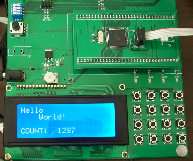
If you want you can blink an LED inside your loop as well, to let you know the loop is running even if your LCD doesn't work. You can even blink the LCD backlight if you have wired it up to a GPIO pin. In any case, here is a picture of the docking board, with AVR plug-in, running the above code:
Some Details As Seen On The Scope
Here is a scope picture of some LCD control and data signals while writing out a string to the display, using busy flag waiting. It may help you to better understand what is happening.
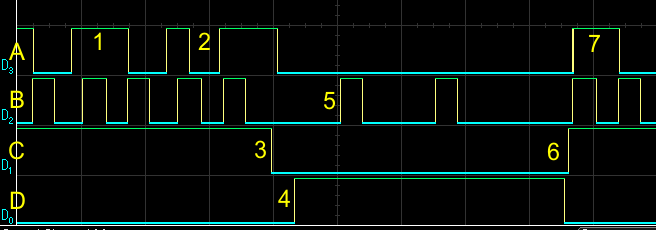
The signals are as follows:
- A: Data bit D7 (also BF)
- B: E pulse
- C: RW signal (Read = 1, Write = 0)
- D: RS signal (Date = 1, Command = 0)
The points of interest are:
- BF still high from last write (1st of the 2 E pulses for each display status read)
- BF now low at the end of 1st of 2 E pulses for next display status read), display is ready
- Switch from READ to WRITE
- Switch from CMD to DATA
- Write one data character using 2 E pulses
- Switch to READ and CMD to start checking for BF
- BF is high (busy) from the just-completed write, keep reading until it goes low
Do We Have Any Potential Data Corruption Issues - AVR Version?
Remember, we must always ask this question when, among other things, we are doing RMW on a GPIO port, as we are doing here. The answer, for the port pins we have chosen, is NO, because we are using the entire 8-bit port for the LCD, and thus there is no possibility that any ISR could be using any of the pins for other purposes. This assumes that we aren't also calling LCD functions in an ISR - that would be a problem! If, on the other hand, we were using, say, 4 bits of one port for data, and 4 bits of another port for control, then it would be quite possible that the other 4 bits of each of the two ports might be used in an ISR, and we would have to check for that. So we did ourselves a favor by using up all the bits of one port for our LCD connections.
The LCD Source Code - STM32 Version
For now I'm not going to show an STM32 version of the LCD code. The main reason is that I have a bit of a trick up my sleeve for the STM32 but it has to wait until the next chapter on timers. The other reason is that it should be a trivial effort to convert the AVR code to STM32 code. This will just involve configuring the appropriate GPIO pins and accessing them as we've already seen, and also figuring new delay values if not using the busy flag.
Do We Have Any Potential Data Corruption Issues - STM32 Version?
We can't say NO as quickly in this case, since STM32 ports are 12 bits wide and we're only using 8 bits. So it is something we would need to keep in mind if and when we assigned any of those remaining 4 port pins. If any of them were manipulated in an ISR, then we would have to protect our LCD port accesses with some form of atomic action. Remember that the STM32 has atomic set and reset registers that we can use, but when it comes to setting the 4 bits of data we can't easily use those (we can, but it would take some additional code), so we would be reduced to turning off the offending interrupt(s) while writing the 4 data bits. The best choice, if possible, would be to assign the remaining 4 bits to duties that did not involve any ISR manipulation.
Next
The next chapter will take another look at timers, and how they might help with our LCD code. After that we will add additional hardware to our setup, and write some software for that hardware.


- Comments
- Write a Comment Select to add a comment
To post reply to a comment, click on the 'reply' button attached to each comment. To post a new comment (not a reply to a comment) check out the 'Write a Comment' tab at the top of the comments.
Please login (on the right) if you already have an account on this platform.
Otherwise, please use this form to register (free) an join one of the largest online community for Electrical/Embedded/DSP/FPGA/ML engineers:


