


OOKLONE: a cheap RF 433.92MHz OOK frame cloner
Introduction
A few weeks ago, I bought a set of cheap wireless outlets and reimplemented the protocol for further inclusion in a domotics platform. I wrote a post about it here:
//www.embeddedrelated.com/showarticle/620.php
Following that, I had access to another outlet from a different vendor:
http://www.castorama.fr/store/Prise-telecommandee-BLYSS---Interieur-prod4470027.html
The device documentation mentions that it operates on the same frequency as the previous product, ie. 433.92MHz. I also suspected the use of OOK modulation.
I wanted to include this new device to the domotics platform, which would imply to redo the same reverse engineering process as before. Then, I had an idea (yes, it happens sometimes ...): would it be possible to make a cheap device that automates the work of listening and cloning a RF data frame, given some initial assumptions (operating frequency, modulation type) ? This is how the OOKLONE project was born.
This post details the current prototype implementation. Note the project repository URL, which I refer to in this post:
https://github.com/texane/ooklone
Also, the current commit is:
201e0be5a281bbef0064ccc6bc7f727f2de0e9a2
From idea to prototype
Hardware
I initially planed to use the RFM22B from HOPERF which I already used in the previous project:
http://www.hoperf.com/rf/fsk_module/RFM22B.htm
I already knew it could send raw OOK modulated frames. However, tests shew it could not receive arbitrary raw frames due to its internal bit synchronizer that expects a fixed preamble sequence. I tried different methods, such as manual RSSI detection but the update rate was too low to be of any use. I gave up with this chipset.
After a look at other RF chipset datasheets, it seemed that RFM69 could do the job. The datasheet mentions that 2 pins give access to the raw OOK demoulated signal data and clock, and that the bit synchronizer can be disabled:
http://www.hoperf.com/rf/fsk_module/RFM69W.htm
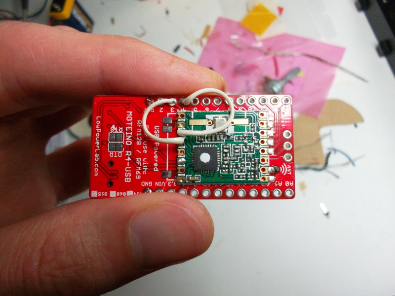
By investigating a bit, I found the MOTEINO platform. It is a simple ATMEGA328P based board connected to a RFM69 which fits perfectly for my purposes:
http://lowpowerlab.com/moteino
By default, the MOTEINO board does not provide access to the demodulated OOK signal data and clock pins. It has to be wired manually:
The MOTENIO is mounted on a carrier board which includes a SMA connector so that I can test different antenna. I also put a SDCARD slot, as a way to store acquired frames and device related configuration.
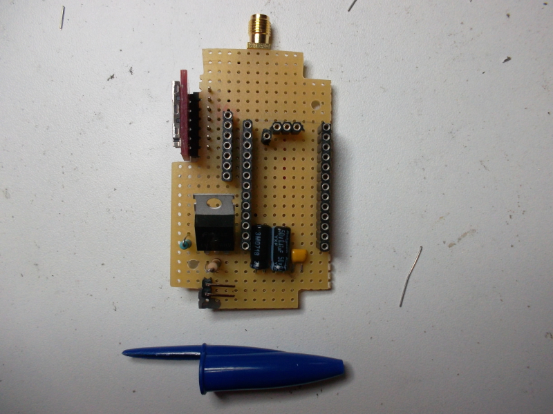
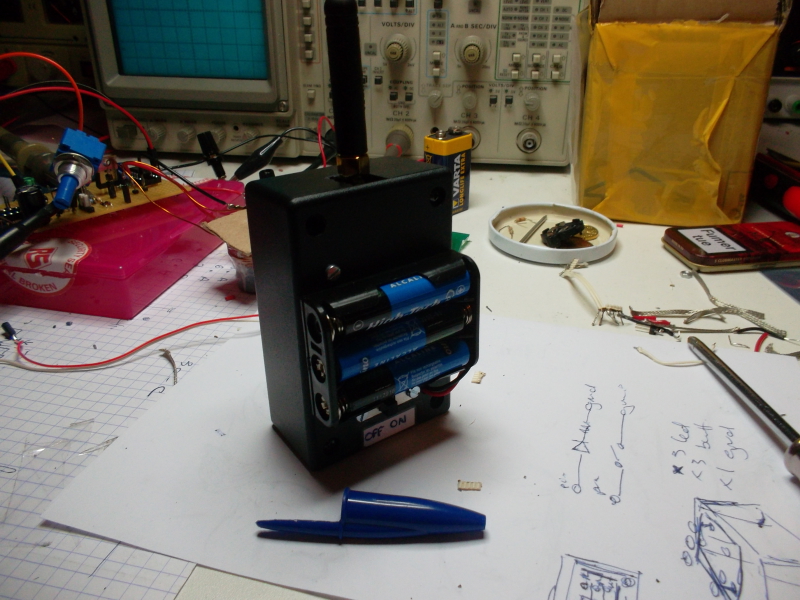
The powering stage consists of 3 LR03 batteries regulated to 3.3V by a LM317. I added tank capacitors to handle the current drawn by the RF chipset.
As a minimal user interface, I added 2 buttons for recording and playing a frame. Here some pictures of the resulting device:
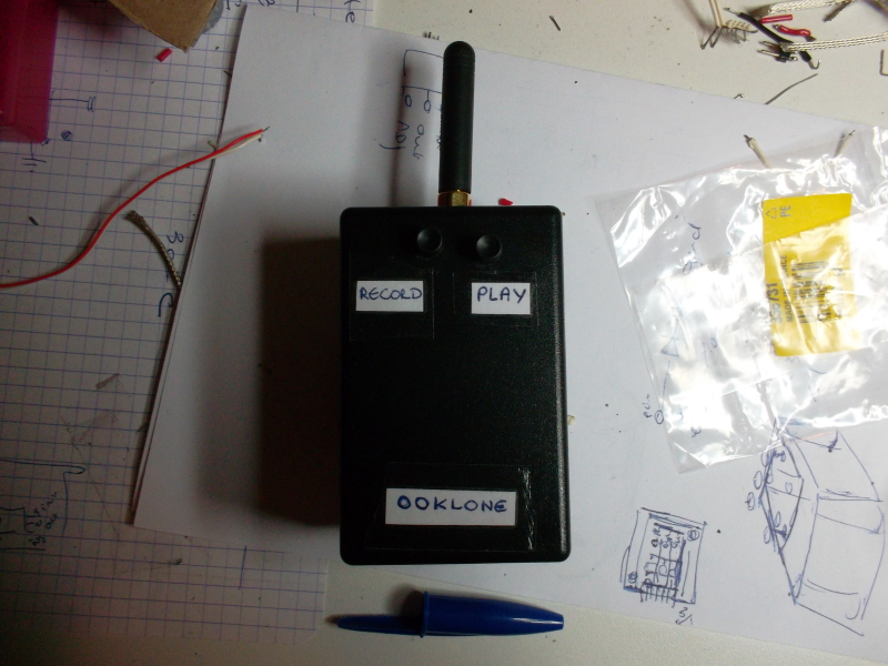
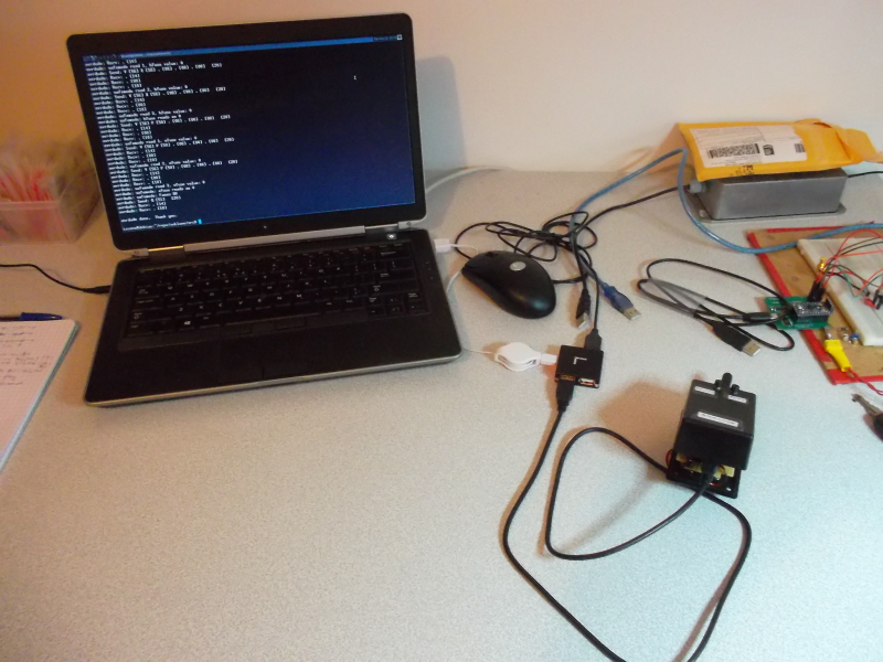
That is all: quite limited for now, but enough to validate and play with the idea in a few days (or rather, nights ...) of work.
Software
The source code is all available in the repository. The file:
https://github.com/texane/ooklone/blob/master/src/rfm69.cimplements the low level routines to communicate with the RFM69 chipset. It uses the SPI hardware module.
The file:
https://github.com/texane/ooklone/blob/master/src/main.ccontains the actual device logic. It is split into 2 parts, both triggered by pressing one of the 2 buttons.
Pushing the record button runs the frame acquisition routine. A loop actively polls the RFM69 OOK data pin and filters eventual glitches. A start of frame is detected when the data pin transits from zero to one. As the pin state changes, an hardware counter is captured and restarted that measures the pulse duration. Pulse durations are 8 bits values stored in a global software buffer. The pulse timing resolution is set to 16 microseconds, which limits the maximum pulse duration to 4 milliseconds.
Pushing the play button runs an automaton driven by the hardware timer interrupt. Starting at pulse 0, it progressively increments an index and set the RFM69 data pin accordingly to the duration previously acquired during frame acquisition.
Testing
I made videos where the device is used to capture and replay frames:
http://youtu.be/vF0f3mg6Mu8http://youtu.be/LgjCQ955Rmc
http://youtu.be/40qgGdyqTsA
http://youtu.be/wpKg1sM68SA
Limitations and more features
Currently, there is only one acquired OOK frame. Also, it is stored in SRAM, and thus lost as the device power shuts down. I initially planed to address these 2 issues by adding a SDCARD. The slot can be seen in the previous pictures. However, the MOTEINO can be shipped with an external serial flash memory, a solution that I would prefer to use.
Another point is that the software OOK frame buffer size is limited by ATMEGA328P SRAM to 1024 pulses. If this constraint is too restrictive, I will eventually drop the MOTEINO board for a more powerful platform, such as the TEENSY3.1 board:
http://www.pjrc.com/teensy/index.htmlSome parameters are fixed in the source code, such as bandwidth, frame blank time and pulse timing resolution. It should be user settable, but would require a richer user interface. I am thinking about it, and any idea is welcome.
The modulation scheme is currently fixed to OOK. While I did not test it, I think it is possible to support FSK. The OOKLONE name would not stick anymore, but that is fine :)
I did not work much on the device powering stage. I will use this prototype to make some measures, and scale both the electronics and software accordingly.
When I am done addressing these points, I will publish schematics and eventual CAO files for the packaging of a more serious version of the device.
That is the project TODO list for now.
Security implications
For sure, being able to duplicate RF frames has security implications. I can not be held responsible for eventual damages that may result from using this device... Ok, I actually do not know what it means, but every project include sentence of this sort. More seriously, I hope people are well educated enough not to unlock their neighbor pre 2000 car. Also note that security minded wireless communication protocols include frame anti replay mechanisms. However, implementing security mechanisms is often a matter of resource tradeoffs, and that is often why they are more or less effective in practice.
Conclusion
While still in the prototype stage, I submitted OOKLONE as an entry to the Hackaday Prize contest:
http://hackaday.io/prizehttp://hackaday.io/project/2403-ooklone
I encourage you to have a look at the entry list, it is huge what people came up with. Also, if you are a bit into the making community, you will be impressed by the judge panel ... looks like Hackaday managed to gather 'The Expandables' team :)
Given its status and what others have built so far, OOKLONE has no chance to win. But it fits both the topic (ie. build a connected device related thing) and the Hackaday community purpose (ie. hacking things). So it was a good opportunity to get involved in this great event.


- Comments
- Write a Comment Select to add a comment
FSK means " " ?
SPI means" " ?
RSSI means" " ?
OOKLONE is " "?
MOTEINO is " "?
I am fortunate enough to know the many other references here and I am very familiar with Arduino and Programming
Perhaps you technical specialists might get the point from this post.

I agree that these terms may not be obvious for non technical people, or
people not in the radio field. However, this is a technical article and I think
it is fair to assume readers know these commonly used acronyms, or at
least know how to get info on them (ie. wikipedia gives a direct answer for
all the ones you mention). For less well known terms (moteino ...), I give
the needed references.
Dude, I didn't understand it all of it but, It's fricken brilliant! I love it! :) why didn't I come up with it?
I'm sitting here considering all the evil things i could and would probably do with it, and honestly? With a few mocdifications I would be a very bad girl indeed.
Good luck to you.
Actually, this is a device with a lot of application, and this is time well
spent. While I focus on RF frame cloning, I made it open source so that
people can use it as a starting platform to implement their own tool.
A guy told that it could be a RF swiss knife, which captures well the idea.
Also, people mentioned, the device is not original since RF cloner already
exist on the market, but I do not know about these device, and I suspect
they are not open source. In the same discussion, note that you can already
achieve the same results using a SDR, which is more costly (>300 dollars)
and bulky.
Speaking of possible (evil ?) applications, I posted a video here:
http://youtu.be/40qgGdyqTsA
Know however that wireless protocol security is now considered very
seriously, and pure frame cloning wont work if anti replay scheme are
implemented correctly.
I ordered a PCB and 3d printed enclosure from SEEEDSTUDIO. I will write a construction guide as soon as I receive and valid the components. I will let you know when it is done.
i have buy it
1 × anarduino69 miniwireless
1 × lm317 Power Management ICs / Linear Voltage Regulators and LDOs
2 × buttons record and play a frame
1 × switch turn the power on off
1 × SMA femal connector allow for testing different antenna
1 × 433MHz SMA antenna antenna
3 × capacitors (2x 470uF, 1x 100nF) tank caps
is this functionality with anarduino69
in the picture are more capacitors can i have a description please.
Thanks for your comments. As I mentioned in my previous reply, I will detail the kit when I receive and check the PCB and enclosure that I will get from SEEEDSTUDIO. Yes, the RF chipset used is RFM69
REVERSE ENGINEERING AND WIRELESS ALARM WITH THE HACKRF
we are not thieves, but the design of the commercial part, we would be interested
Thanks.
Greetings fy MARKET.SK Director
juro@onicom.sk
all the project materials are available here:
https://github.com/texane/ooklone
I can do consulting if needed, contact me on my
email address for that.
Cheers,
fabien.lementec@gmail.com
You believe that you can read the protocol with rfm69 weather station Auriol ? I know that uses the OOK .
http://www.tfd.hu/tfdhu/files/wsprotocol/auriol_protocol_v20.pdf
Thanks for the comments. It seems the frames can be
captures by OOKLONE. However, I do not see the point
of replaying it ...
Cheers,
sorry for my english , i do my best
so can you explain me how to program my moteino i don't arrive to implement the sketch
i need a step by step tutorial
thanks
To upload the firmware on the moteino, you must ensure avr-gcc is installed on your machine. Then, you go to the src/ directory. Then, compile the firmware by running make. Then, you must upload the produced firmware using ./upload.sh. You must be root to upload, generally. Hope it helps,
I am teacher of computer science and small amateur programme planner, me life in France, j love your blogs and j will like to try to reproduce the ooklone, not for l to use but only to try to include all detailles for a bigger knowledge because I am not trés token in programation :)
here is my direct mail because there is a sencure a lot:vezia.arnaud@hotmail.fr.Pouvez to give me to you all detailles for m to help has accomplish him, because all your links were erased.
finally if you want it, on!
warmly Arnaud
To post reply to a comment, click on the 'reply' button attached to each comment. To post a new comment (not a reply to a comment) check out the 'Write a Comment' tab at the top of the comments.
Please login (on the right) if you already have an account on this platform.
Otherwise, please use this form to register (free) an join one of the largest online community for Electrical/Embedded/DSP/FPGA/ML engineers:


