


Cortex-M Exception Handling (Part 2)
The first part of this article described the conditions for an exception request to be accepted by a Cortex-M processor, mainly concerning the relationship of its priority with respect to the current execution priority. This part will describe instead what happens after an exception request is accepted and becomes active.
PROCESSOR OPERATION AND PRIVILEGE MODE
Before discussing in detail the sequence of actions that occurs within the processor after an exception request has been accepted it is necessary to delve deeper into the concept of processor execution mode.
From this point of view the Cortex-M processor’s approach is fortunately much simpler than the ones of its predecessors. For instance, the ARM7TDMI processor, once very popular as a microcontroller’s building block and designed according to version 5 of the ARM architecture, has seven distinct modes of operation (of which two, interrupt and fast interrupt, are for interrupt handling). By contrast, Cortex-M processors only have two modes in total, called thread and handler mode.
Another point worth mentioning is that Cortex-M processors implement two distinct stack pointers, called Main Stack Pointer (MSP) and Process Stack Pointer (PSP) and referring to distinct stacks in memory. At any given time, the processor makes use of one of them, and the choice also depends on the execution mode.
Knowing exactly which stack pointer is in use is extremely important for embedded software developers, because stacks hold critical data structures, such as function arguments and return values. Moreover, when the system supports the concurrent execution of multiple tasks, proper stack management (which is a per-task data structure) is crucial to avoid memory corruption and ensure that the system operates correctly.
Thread mode
Thread mode is the normal task execution mode and—as an exception to the general rule to be discussed later—is also the mode entered by the processor when it accepts a reset exception. From the point of view of execution privilege, thread mode can be either unprivileged or privileged, depending on how the nPRIV bit of the CONTROL register is set.
Execution privilege determines the extent to which the currently executing code is allowed to access and make use of system resources, namely, some critically-important instructions, registers, and memory areas. For instance, the CONTROL register itself can be written only by privileged code. This makes sense, otherwise non-privileged code could easily raise its privilege level in an uncontrollable (and even undetectable) way by overwriting the current contents of CONTROL with a more favorable value.
Instead, only the processor hardware itself—according to mechanisms we will more thoroughly describe in the following—as well as privileged code are allowed to modify CONTROL. When this feature is accompanied by a suitable memory protection mechanism (like the MPU briefly outlined in the first part of this article), it becomes possible to keep a clear and unbreakable separation between code meant to be unprivileged (untrusted application-level code) and privileged code with full access to the system (trusted components, usually part of the operating system).
Another bit of the CONTROL register—namely, the SPSEL bit—decides whether the processor uses the MSP or the PSP as stack pointer when in thread mode.
Handler mode
As its name says, this mode is used by the processor to execute all exception handlers except—as noted above—the reset handler. Code executed in handler mode is inherently privileged and always makes use of the MSP, regardless of the setting of the CONTROL register.
As described in more details in the following, transitions from thread to handler mode take place automatically when the processor accepts an exception request, making it become active, while it is executing in thread mode. The reverse transition, back to thread mode, occurs when an exception handler returns, there are no other active exceptions, and exception handling interrupted the processor while it was executing in thread mode.
A peculiar case of mode transition happens when unprivileged code running in thread mode executes a SVC assembly instruction that, as described in the first part of this article, triggers an exception request unconditionally. The exception is accepted synchronously with respect to the current instruction flow and grants unprivileged code controlled access to privileged execution mode, by means of trusted software routines usually implemented within the operating system.
WHAT HAPPENS WHEN AN EXCEPTION BECOMES ACTIVE?
The main phases that make up the exception handling entry sequence—that is, the sequence of actions performed by the processor to start handling an exception—are depicted in the figure that follows and then discussed in detail. The numbers in the figure correspond to the ones in the explanation.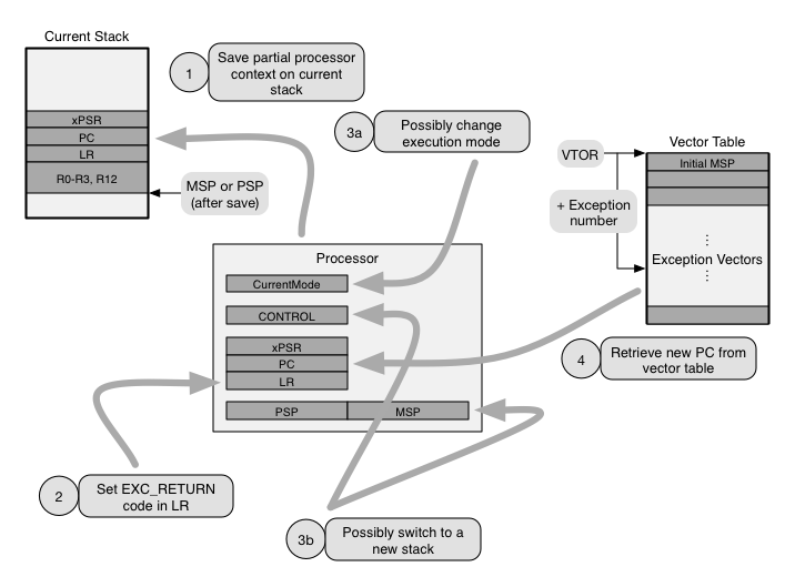
- The first action performed by the processor is to save part of the current execution context. This information is stored on the current stack, that is, the stack that the processor is using when the exception request is accepted. The minimum amount of information that is saved into a basic stack frame consists of registers R0 through R3, R12, the link register LR (also accessible as R14), the program counter PC (R15), and the program status register xPSR, for a total of 32 bytes.
When the processor implements the optional floating-point extension, the context of the floating-point unit is saved as well, into an extended stack frame. This part of the context may either be saved immediately during the entry sequence, as described above, or be postponed as much as possible, until when the context is about to be modified by the execution of a floating-point instruction. This is because the floating-point context is rather large and requires 68 additional bytes.
More information about this form of lazy context save and restore technique—which is also widespread, with minor variations, in other families of processors—is left as a topic of a future post. Instead, in the following, we will focus only on how processors without floating-point extension behave.
In both cases, depending on the value of the STKALIGN bit of the Configuration and Control Register CCR, the processor may adjusts the stack pointer to make sure that the saved stack frame is aligned to a multiple of 8 bytes.
The reason behind saving the execution context is that accepting and handling an exception shall not necessarily prevent the processor from going back to its current activity at a later time. This is particularly true for interrupts and other exception requests that occur asynchronously with respect to current processor activities and are most often totally unrelated to them. Thus, they shall be handled transparently with respect to any code that happens to be executing when they arrive.
On the other hand, the choice of which part of the context is saved is motivated by the goal of making the resulting stack frame layout compliant with the ARM Architecture Procedure Calling Standard (AAPCS). In this way, any AAPCS-compliant function can be used as an exception handler. This is especially important when exception handlers are written in a high-level language because compilers are able to generate AAPCS-compliant code by default, and hence, they can also generate exception handling code without treating it as a special case.
In other words, the processor hardware saves the context on the stack exactly like an AAPCS-complaint software procedure does when it is about to call another. As a result, an exception handler call performed by hardware is indistinguishable from a regular software-managed function call. - Set the link register LR to an appropriate exception return value (called EXC_RETURN value in the ARM documentation). As it will be better discussed in the following, when an exception return value is loaded into the program counter PC, as part of a function epilogue, it directs the processor to initiate an exception handler return sequence instead of simply returning to the caller.
In fact, the AAPCS stipulates that a function call must save into the link register LR the return address, before setting the program counter PC to the function entry point. This is typically accomplished by executing a branch and link instruction BL with a PC-relative target address. It is worth mentioning that, when the processor supports multiple instruction sets, bit 0 of LR assumes a special meaning and indicates the instruction set in use at the time of the call. However, this is not the case in Cortex-M processors, which only support the Thumb-2 instruction set.
In the epilogue of the called function, it is then possible to return to the caller by storing back into PC the value stored into LR at the time of the call. This can be done, for instance, by means of a branch and exchange instruction BX, using LR as argument. Hence, once again this aspect of the exception entry sequence has been architected to permit any AAPCS-compliant function to be used directly as an exception handler.
The information provided by the EXC_RETURN value allows the processor to locate the stack frame to be restored, interpret it in the right way, and bring back the processor to the execution mode in effect when the exception was accepted. To this purpose, as shown in Table 1, the 5 low-order bits of the EXC_RETURN value encode:- whether the processor is using the main (MSP) or process stack pointer (PSP);
- whether the saved stack frame is basic (not including room for the floating-point context) or extended (including it);
- the current processor execution mode (thread or handler mode).
The remaining bits, namely, bits 27 down to 5, are unused at this time. They all read as one currently, but software must preserve their value when writing. It should be noted that the processor analyzes the value being loaded into PC and possibly interprets it as a EXC_RETURN value only in specific cases, better detailed in the Cortex-M architectural documentation and associated with exception handler epilogues.
In other cases, for instance when PC is loaded while the processor is in thread mode (and hence, no exception handler can possibly be active), the value is taken literally, as a memory address. To avoid improper behavior if an EXC_RETURN value is mistakenly loaded into PC in these cases, the hardware protects address range 0xF0000000–0xFFFFFFFF against instruction execution. - Possibly switch to handler execution mode, if the processor was executing in thread mode when the exception was accepted. A notable deviation from this general rule is the reset exception, which is handled in thread mode instead. Associated to the execution mode switch, the processor may also transition to use a new stack. In fact, as mentioned previously, handler mode execution always makes use of MSP, whereas thread mode execution may use either MSP or PSP, depending on processor configuration. Upon reset, execution starts in thread mode and the processor is automatically configured to use MSP.
Additional operations performed by the processor, neither shown in the figure above, nor further discussed here, include storing the exception number of the exception just accepted in the IPSR sub-register—that is part of the xPSR register—and updating several System Control Space (SCS) registers to reflect exception acceptance. Yet another action is that accepting an exception clears the local per-core state of any pending synchronization instructions, namely, LDREX and STREX. Therefore, any synchronization procedure using those instruction that was pending upon exception entry will need to be repeated after execution resumes. This topic is extremely important for proper inter-core synchronization in multicore systems. - The very last action performed by the processor upon exception entry is to retrieve the target PC—that is, the entry point of the exception handler—from the vector table and jump to it.
The vector table is a very simple, memory-resident data structure and consists of an array of 32-bit integers, holding memory addresses called vectors. More specifically, the i-th entry of the table holds the entry point of the handler for exception number i. No ambiguity can arise from this assignment because exception numbers are fixed and, unlike priorities, uniquely identify each exception.
Only the first 16 exception numbers are explicitly defined by the architecture specification. Also, the total number of vectors is not fixed and depends on the number of exceptions supported by specific members of the Cortex-M family, as well as configuration and implementation options. The very first entry (at index 0) is used in a special way because, in fact, no exception is ever assigned exception number zero. Instead, this entry contains the initial value loaded into MSP upon reset.
The starting address of the vector table is held in a register called Vector Table Offset Register (VTOR). The 7 low-order bits of VTOR are reserved and are always interpreted as zero, because the minimum alignment of the vector table in memory is 128 bytes. In addition, further alignment constraints may come into effect, depending on the total number of entries in the table.
Unlike, for instance, the previously mentioned CONTROL register—which is tightly coupled to the processor and is directly accessible to it by means of the specialized instructions MRS and MSR—VTOR is a memory-mapped register and the processor gets access to it through regular memory load and store instructions, like LDR and STR.
For this reason, to protect VTOR against unauthorized write accesses (for instance, write attempts made by unprivileged code) it is necessary to enable a suitable memory protection mechanism, mentioned in the first part of this article, and configure it appropriately. Alternatively some processors, like the Cortex-M3, which do not implement those programmable mechanisms, may still support non-programmable protection, and prevent uncontrolled access to VTOR, as well as other critical memory-mapped registers, from unprivileged code.
Another point worth mentioning is that the VTOR register is reset to zero when the processor accepts a reset exception. As a consequence, the initial values of PC and MSP upon reset are not retrieved from the current vector table, that is, the one in effect when the reset exception was accepted, but from the vector table at address zero.
It should also be noted that, depending on the specific device, the physical address of the vector table may be further affected by address remapping, external to the processor. In those cases, it is necessary to refer to the device—rather than the processor—documentation to ascertain which registers control the mapping and how.
For instance, in the the NXP LPC17xx microcontroller family it is possible to map at address 0x00000000 (where the vector table begins by default) the bootstrap ROM (which is normally accessible at physical address 0x1FFF0000) instead of the on-chip flash memory (which actually resides at address 0x00000000). Remapping is controlled by bit 0 of the device-specific MEMMAP register.
Table 1
Encoding of The EXC_RETURN Value
| EXC_RETURN value (5 low-order bits) | Stack Pointer | Frame Type | Execution Mode |
|---|---|---|---|
|
11101 (0x1D) |
Process | Basic | Thread |
|
11001 (0x19) |
Main | Basic | Thread |
|
10001 (0x11) |
Main | Basic | Handler |
|
01101 (0x0D) |
Process | Extended | Thread |
|
01001 (0x09) |
Main | Extended | Thread |
|
00001 (0x01) |
Main | Extended | Handler |
| Other | Reserved | Reserved | Reserved |
EXCEPTION RETURN
As stated previously, the processor starts an exception return sequence when a special value—characterized by the pattern 0xF in the 4 higher-order bits and called EXC_RETURN in the following—is loaded into the PC at the end of an exception handler.
Informally speaking, in these cases, instead of simply overwriting the old contents of the PC and jump to the new address, the processor “undoes” the exception handler activation steps described previously in order to transparently resume the activity it was performing when the exception became active. More specifically:
- First of all, the processor examines and interprets the EXC_RETURN value according to Table 1 above. More specifically, the value determines which stack pointer (MSP or PSP) will be used to restore the processor context in the next steps, the struc- ture and contents of the stack frame to be restored (basic or extended), and the processor mode (handler or thread) after restoration.
- Then, the processor performs several integrity checks to ensure that returning from an exception is legal considering the current execution context. Any failed check raises a UsageFault exception, which is then handled as usual.
For example, the exception currently being handled, whose number has been recorded in IPSR upon exception entry, must be active in order to legitimately return from it. Furthermore, the processor must currently be executing in handler mode and, if it is about to return to thread execution mode, the value to be restored into IPSR must be zero, thus indicating that no exceptions are active any more. A thorough discussion of all checks is beyond the scope of this book, and interested readers should refer to the Cortex-M architectural documentation for further details. - Finally, the processor restores the context stored in the stack frame indicated by the stack pointer identified in the previous step. Among other things, the context includes the exception number being handled when the current exception was accepted in the IPSR sub-register of xPSR, and the PC where the exception being concluded was accepted.
Therefore, a direct consequence of context restoration is that the processor resumes execution from where is was previously suspended and IPSR contains the exception number of the exception whose handling is being resumed, if any. If exceptions were not nested, IPSR is restored to zero instead.


- Comments
- Write a Comment Select to add a comment

https://www.youtube.com/playlist?list=PLPW8O6W-1chwyTzI3BHwBLbGQoPFxPAPM
Hello,
I am using cortex M4 controller.
I am in a situation where a low priority ISR is interrupted by High priority ISR and from HPI i want to go to the next ready task.
But because the LPI is still active when i try to go to new task(thread mode) from handler mode i get a USAGE FAULT.
How can i go to thread mode in this situation?
How can the Active state of Low priority ISR be changed in HPISR ?
Regards,
Yuvraj

Hello,
as you point out, the processor does not normally support returning to thread mode when at least one exception other than the returning exception is active, as stated in "Integrity checks on exception return", Section B1.5.8 of the ARMv7-M Architecture Reference Manual.
This is for good reasons, better explained in Section B1.5 of the same manual, related to stack management/integrity and consistent handling of task and interrupt handler priorities.
The check can be disabled by setting bit NONBASETHRDENA of the Configuration and Control Register (CCR), Section B3.2.8 of the same manual.
However, before doing that, I would consider the side effects of this decision carefully. For instance, when is the LPI going to be resumed and how? Where is its execution context kept in the meantime? What about priority inversion?
I hope this answers, at least partially, your question.
Regards,
ICB
Hello,
Thank you very much for the suggestion.
Yes, I tried with setting NONGASETHRDENA bit but as you said this will not deactivate the interrupt and the LPI will not be able to be activated again.
The other solution i see is to set a Flag in HPI and switch to start of LPI and check the Flag and then switch the context to next ready task.
Regards,
Yuvraj
You are right, there are side effects and that's why I was a bit reluctant to suggest that approach. I do have in mind a couple of scenarios where it is indeed necessary, but they are very complex and I am not sure this is your case.
If I understand your solution correctly, there may be side effects too, depending on how complex the LPI is. For instance, if the LPI updates (non atomically) a complex data structure and it is restarted from the beginning (instead of resumed), this may easily lead to inconsistencies because LPI may leave the update "midway".
That's why, in virtually all traditional RTOS, interrupts are accepted in priority order, handlers are executed in a LIFO fashion (holding their context on a single interrupt stack), they are resumed when preempted, and always run to completion. They all implicitly have a priority higher than any task in the system, too.
Assuming your issue is that a task T needs an execution priority lower than HPI but higher than LPI, the "textbook" solution is to split LPI into two parts: an interrupt handler LPI' and a task LPT. LPI' only wakes up LPT and is extremely short, so that its execution does not disrupt timings. You can then give LPT the priority you prefer, lower than T.
Most RTOS provide native mechanisms to support this (one example for all, ISR/DSR in eCos), but it's also ok to use a semaphore/event flag. Most RTOS can wake up a task waiting on a semaphore/event flag in a couple of assembly instructions, and hence, LPI' is very short indeed.
Have a nice day,
Ivan
Hello Ivan,
Thank you very very much.
Regards,
YUVRAJ
Hello,
I am working on cortex M4 and currently i am in a situation where in from the interrupt (exception) routine I want to enter into thread mode and execute a function and then again return back to handler mode. When i enter into thread mode (By changing the PSR register and using BX instruction ) the the IPSR register is cleared but active exception becomes pending.
What can be the reason that the Active exception becomes pending ?
Regards,
Yuvraj

Hi Yuvraj,
a better place to ask questions like this would be in the forums. Maybe Ivan will answer you here, but I believe Ivan also pays attention to the forums and you would get the extra benefit of having other users who could contribute to the discussion.
Stephane
Hello Stephane,
Yes, I will use the Forum for the discussion.
Thank you very much for the information.
Regards,
Yuvraj
To post reply to a comment, click on the 'reply' button attached to each comment. To post a new comment (not a reply to a comment) check out the 'Write a Comment' tab at the top of the comments.
Please login (on the right) if you already have an account on this platform.
Otherwise, please use this form to register (free) an join one of the largest online community for Electrical/Embedded/DSP/FPGA/ML engineers:


