


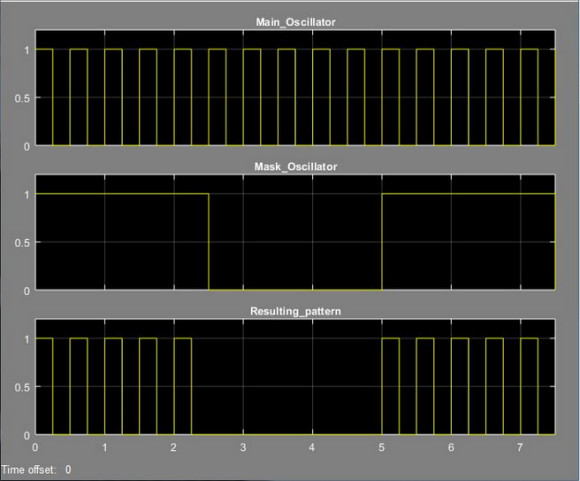
I have decided to implement this with two software oscillators. The first oscillator produces pulse signal with period 500 ms. The second one produces pulse signal with period 5000 ms. The outputs of both oscillators are processed by logic AND for resulting signal.
The software oscillator is implemented in following manner. There is one function called OSC in my source code and the individual instances are modeled by C struct.
typedef struct{
float period; // period of the oscillations (ms)
BOOL start; // oscillator start signal (start==TRUE, stop==FALSE)
BOOL init; // init==TRUE, initialize timer
float delta; // timeout for negation the output
uint16_t start_time; // captured state of the appropriate system timer
uint16_t cycle_cnt; // current cycle count
TIMER tmr; // used system timer
}Osc_t;
void OSC(uint32_t output, Osc_t *p){
uint16_t act_time;
uint16_t elap_time;
// oscillator start required?
if(p->start){
// reading value of system timer
taskENTER_CRITICAL();
switch(p->tmr){
case T1MS:
act_time = Tmr_1ms;
break;
case T10MS:
act_time = Tmr_10ms;
break;
case T100MS:
act_time = Tmr_100ms;
break;
}
taskEXIT_CRITICAL();
// capture current state of appropriate system timer
if(p->init){
p->start_time = act_time;
p->init = FALSE;
}
// half period based on desired period and system timer used
switch(p->tmr){
case T1MS:
p->delta = ((p->period)/2);
break;
case T10MS:
p->delta = ((p->period)/(2*10));
break;
case T100MS:
p->delta = ((p->period)/(2*100));
break;
}
// current elapsed time
elap_time = (act_time - (p->start_time));
// half period elapsed?
if(elap_time >= (p->delta)){
// one cycle
if(TestIfLogicSignalSet(output)){
p->cycle_cnt++;
}
NegLogicSignal(output);
p->start_time = act_time;
}
}else{
ClearLogicSignal(output);
p->cycle_cnt = 0;
p->init = TRUE;
}
}
I have defined several global variables ("software timers") called Tmr_1ms,
Tmr_10ms and Tmr_100ms for timing purposes. These variables are incremented in
an ISR which is invoked every 1 ms
// 1 ms counter
Tmr_1ms++; // 0 ms - 65535 ms
// 10 ms counter
if(++cnt_01 == 10){
Tmr_10ms++; // 0 ms - 655350 ms
cnt_01 = 0;
}
// 100 ms counter
if(++cnt_02 == 100){
Tmr_100ms++; // 0 ms - 6553500 ms
cnt_02 = 0;
}
The software timer used by oscillator instance is determined by TIMER tmr item
in Osc_t struct.
// system timers
typedef enum{
T100MS,
T10MS,
T1MS
}TIMER;
The complete implementation is following
// main oscillator init
Main_Oscillator_state.period = 500; // 500 ms
Main_Oscillator_state.tmr = T1MS;
Main_Oscillator_state.init = TRUE;
// mask oscillator init
Mask_Oscillator_state.period = 5000; // 5000 ms
Mask_Oscillator_state.tmr = T1MS;
Mask_Oscillator_state.init = TRUE;
Main_Oscillator_state.start = TRUE;
Mask_Oscillator_state.start = TRUE;
// main oscillator
OSC(LMainOsc, &Main_Oscillator_state);
// mask oscillator
OSC(LMaskOsc, &Mask_Oscillator_state);
// resulting alarm blinking pattern
AND_02(LBlinkPat, LMainOsc,DIR, LMaskOsc,DIR);
The problem is that this implementation is functional only in case I place
the OSC and AND_02 functions into ISR which is invoked every 1 ms. If I place
these functions into ISR which is invoked every 20 ms there are errors in
blinking pattern (the first and fifth pulse in the resulting pattern have
sometimes shorter duration). Does anybody have any idea what could be the reason? I need to place the OSC and AND_02 functions call into 20 ms ISR.
My idea was that this inaccuracy is caused by reading the Tmr_1ms in 20 ms ISR
and the fact that the half periods of the oscillations are 250 ms (= 12.5*20 ms i.e. not integer multiple of 20 ms) and 2500 ms (= 125*20 ms).
Why are you using such a complicated method to flash an LED in a simple pattern? There are much simpler ways to do it. Is there some requirement that you haven't mentioned?
Hello MarkDSylva, thank you for your reaction. My intention is to have some library of "logic blocks" which mimic the logic hardware for future use in other projects.


