


Hi
I am trying to design a PID controller to control the temperature of a peltier device. The power is controlled using an Analog device ADN8831 device. I have a thermistor connected to the cool side of the peltier and the hot side connected to a heat sink. I have got the controller running using just proportional control. I want to use the Ziegler Nichols method to tune it. So I am trying to get the a state where I have sustained oscillations. But all I can seem to get is sporadic oscillations. I have tried a number of different gains, but none seem to produce a smooth oscillation. I have the sample rate at 32Hz currently.
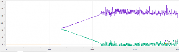
The purple is the measured temp, green error and orange set point. I dont really know much about PID control so if someone could suggest what may be the issue then I would appreciate it. Thanks Jon
Hi, I see your steady state is noisy, to fix out that you could try a wash-out filter in the sense signal, this is going to eliminate the high frequencies on your signal.
jbean - One important piece of information I don't see is how the output is changing, large output swings can be causing your jitter. And can we assume that the x scale is in seconds?If your output is swinging from full off to full on that might be causing your jitter so you might not want to filter that out as it is real data and not system noise. Your temperatures look fairly smooth until you are close to setpoint where I assume you start changing the output value ...
I have written a PID autotune using Ziegler-Nichols closed loop response and what I found is that you need to set the high and low output response values so that they do not cause large scale swings in the process value. So when the PV goes to setpoint plus a small percentage the output goes to the lower value, then when the PV is at SP minus a small percentage you set the output to the higher value.
Hi. The x scale is the sample rate. So each value is 1/32Hz. Here is the image with the power included (red line). I dont really have much knowledge of PID controllers. I guess the power after the initial ramp up, does seem to swing around a lot. But is that caused by the temp sensor, or is the fact that the power is swinging causing the thermistor to swing?

The swinging of the temperature seems to be due to how radically your output is changing, it looks like either the tuning constants you are using are too aggressive, too much integral or not enough derivative which causes the output to change too much in response to the calculated error.
One solution would be to store a table of temperature values and only act on an average of the error over time. This will also allow you to calculate an average slope for calculating the contribution of the derivative term. Another suggestion would be to slow the response of your system down, only calculate a new output value once per second for example. Your system appears to respond very quickly so 1 second might be too slow ...
You have a fast responding system so you will probably have to work with different values of how deep your history of temperatures are and how often you recalculate new output values to get it more stable. I work with commercial cooking equipment which certainly do not respond quickly so I have more latitude in how fast I need to repond to temperature changes.
One good note, your temperature IS oscillating around your setpoint so your algorythm does seem to be working, its tuning the PID values and your response time which needs some more work :-)

The slope of any regular oscillation will be equal to or less than the slew limit which is likely also the initial power-on slope. In your plot you may have about one cycle of oscillation buried in that noise.
At the moment I am only using a P controller, so no I or D. Sorry I maybe didnt make that clear.
Hi,
It seems that this "oscillation" is not really oscillations but only electrical noise. This is probably due to the voltage transients generated by the PWM power switching. This noise is no significant while the PID is saturated because the PWM ratio is probably at 100% creating a continuous voltage with no transients. You can reduce this noise by placing a capacitor in parallel with the analog input of your system to make a RC filter. Depending on your thermistor reading circuit the "R" term might have various value. You can calculate the C value with C = 1/(2*pi*f*R). I suggest to put f as low as possible i.e. 1Hz.
I hope it will help you.

Hello,
What I observe is when error is high the noise is minimum and the controller is functioning thoroughly. But when error approaches zero, noise is dominating.
It may be due to quantization error, please looking to minimizing that. You may need 12 bit quantiztion but you may have applied 8 bit quantization.
Best Regards,
BV Ramesh.

First of all, what you're seeing is not "sporadic oscillation," but noise, pure and simple. It seems to me you need to get the signals calmed down before you start thinking about PID control, or even P. If you can't get a smooth output response from the controller chip, I can't think of any reason to close the loop.
Just to be clear, this is an all-analog circuit, right? You're not sampling anything with a microcontroller or any such?
Yet the ADN8831 seems to be full of oscillators and choppers and all manner of stuff with discontinuous things going on. Including at least two ways to set the oscillator frequency.
Color me old fashioned. When I think of a feedback amplifier, I'm expecting one input and one output. This thing has 33 pins! I'm sure they all have a purpose. But have you worked with this device before? Maybe AD has some tech notes that might help?
One last thought: I see that the 8831 has a response time measured in nanoseconds, but your thermistor's response time is more likely on the order of seconds. So please tell me you've got a low-pass filter between the sensor and the controller.
A Sallen-Key filter makes a great 2nd-order filter, but being a simple man, I'd start with an RC filter with a cap as big as all outdoors.
Jack
Hi Jack, thanks for your comments.
I am using a microcontroller to control the 8831. There is a DAC that outputs a voltage that is input into the 8831 that then changes the 8831 output voltage, and hence the TEC voltage. Then I have a thermistor connected to the TEC and then using the internal opamp of the 8831, a voltage is created that corresponds to the temperature. So I am trying to control the TEC digitally. I can manually control the TEC voltage from the DAC so I know that part is working fine. But when I try and implement proportional control that is when I get the issues. I will put on a scope on the thermistor output and see what the voltage looks like while I keep the TEC volatge at a fixed level.
Jack, looks like you were correct. If I change the control voltage to the 8831 rapidly then the output starts oscillating rather than being a steady voltage. This is then picked up by the thermistor. I think I need to avoid making large voltage transitions. Jon
Outstanding!! Sounds like you're on your way to a cure.
Jack


